Settings for the automatic configuration
(Master TwinCAT 2.11 R3)
The EP7211 offers the option of automatically configuring the connected motor from the AM81xx series. The electronic identification plate integrated in the motor is read and the necessary parameters of the box are adapted accordingly.
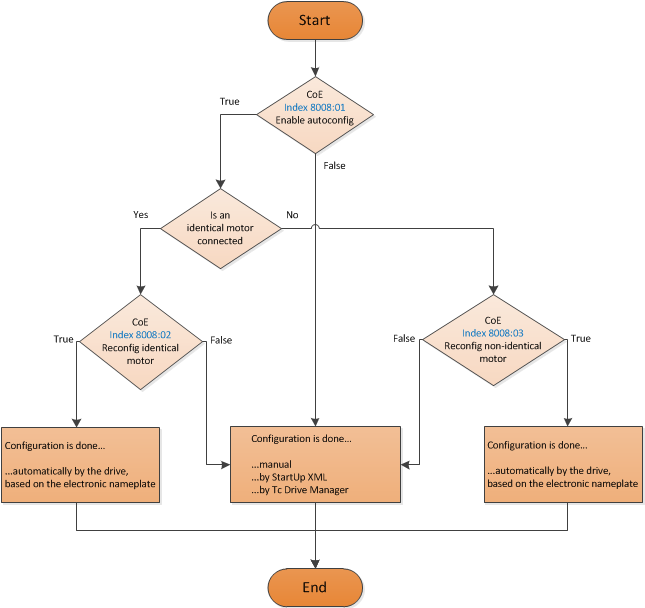
The automatic configuration is switched off on delivery. The user has the possibility to adapt the automatic configuration according to the flow chart shown below (see fig. Flow chart for the automatic configuration).
 | Overwriting of the parameters during automatic configuration The parameters manually changed by the user in the parameter list of the automatic configuration are automatically overwritten at the next start-up if automatic configuration is switched on. |
- The automatic configuration can be switched on in the index 0x8001:01 (0x2018:01, DS402 Profile) Enable autoconfig.
- In the index 0x8008:02 (0x2018:02, DS402 Profile) Reconfig identical motor, the user can decide in the case of replacing an identical motor whether the box should automatically re-configure the motor (setting = true) or whether the motor should be operated with the stored settings (setting = false). The deactivation of this function can be advantageous, for example, if the user has specially adjusted the motor to his application and does not want to lose these settings after replacing the motor.
- In the index 0x8008:03 (0x2018:03, DS402 Profile) Reconfig non-identical motor , the user can decide in the case of replacing a non-identical motor whether the box should automatically re-configure the motor (setting = true) or whether the motor should be operated with the stored settings (setting = false).
Parameter list of the automatic configuration
The following parameters are affected by the automatic configuration.
Index (hex) | Name | Meaning | |
|---|---|---|---|
MDP 407 Profile | DS402 Profile | ||
Current loop integral time | is calculated according to the symmetrical optimum | ||
Current loop proportional gain | is calculated according to the symmetrical optimum | ||
Max. current | is adopted directly from the electronic identification plate of the connected motor | ||
Rated current | is adopted directly from the electronic identification plate of the connected motor | ||
Motor pole pairs | is adopted directly from the electronic identification plate of the connected motor | ||
Commutation offset | is always set to -90° | ||
Torque constant | is adopted directly from the electronic identification plate of the connected motor | ||
Rotor moment of inertia | is adopted directly from the electronic identification plate of the connected motor | ||
Winding inductance | is adopted directly from the electronic identification plate of the connected motor | ||
Motor speed limitation | Calculation of the max. speed of the connected motor | ||
Motor temperature warn level | is adopted directly from the electronic identification plate of the connected motor | ||
Motor temperature error level | is adopted directly from the electronic identification plate of the connected motor | ||
Motor thermal time constant | is adopted directly from the electronic identification plate of the connected motor | ||
Release delay | is adopted directly from the electronic identification plate of the connected motor | ||
Application delay | is adopted directly from the electronic identification plate of the connected motor | ||
Brake moment of inertia | is adopted directly from the electronic identification plate of the connected motor | ||