Module placement
The EJ-Module line shall begin on the left side of the single distribution board with the coupler (or RJ45 plugs) followed by a power supply and IO-modules.
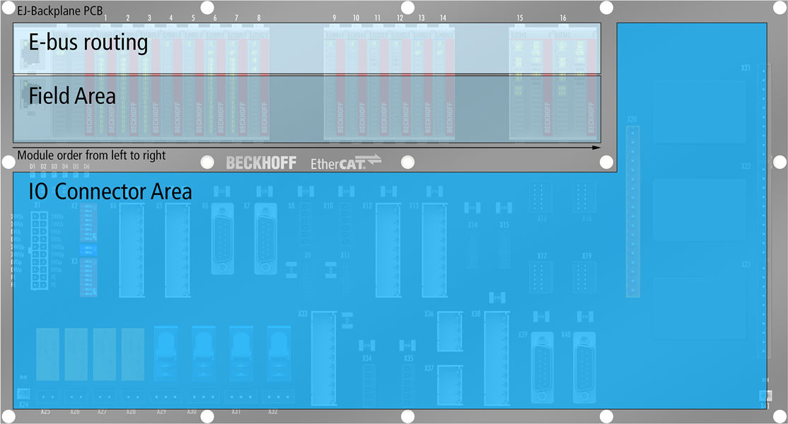
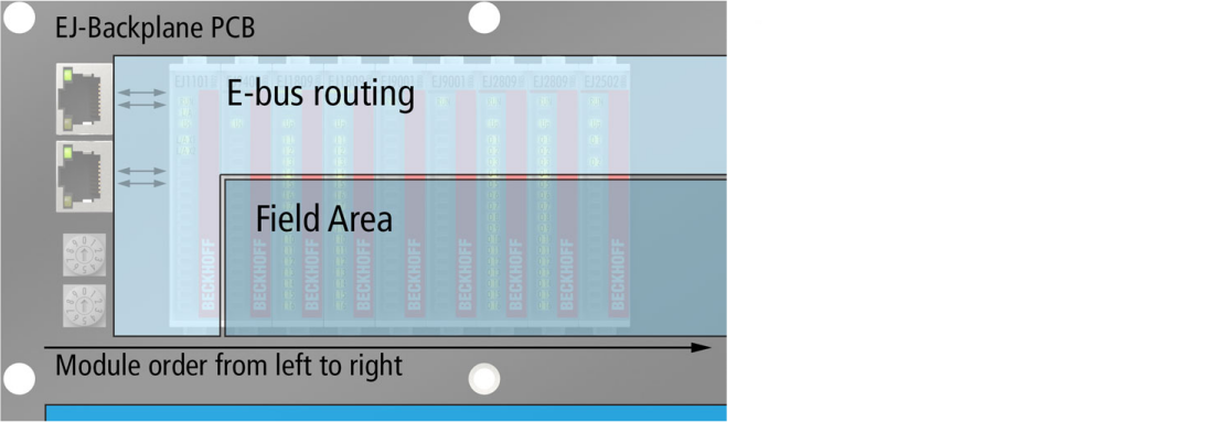
In order to avoid electromagnetical interferences on the E-bus it is not recommended to route IO-connection signals through the E-bus routing area marked in the following figures.
 | Notes for routing Follow the instructions for routing in chapter Design of power supply and Routing guidelines! |
Example with coupler EJ1100
Example with coupler EJ1101-0022 and power supply module EJ9400
An additional power supply module (e.g. EJ9400) and RJ45 sockets are required when using coupler EJ1101-0022. The RJ45 sockets should be placed near the coupler.
Crossing the EtherCAT RX/TX lines between the coupler and the modular jacks with signals that may carry electromagnetical interference shall be avoided.
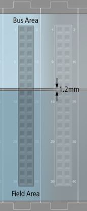
Clearances and creepage distances
Between field and E-bus signals clearances and creepage distances have to be taken care of. A Clearence of 1.2 mm is recommended.