How a transformation axis works
The mechanical solution for some axis types requires the design of a non-linear lever mechanism. The tool path does not follow the drive movement in a constant ratio. This enables the optimization of axis properties for varying requirements in individual areas of the travel. For the best possible embedding of this non-linearity, this design must be represented accordingly by a suitable software concept.
Typical mechanics for a transforming axis would be:
Abstracted circuit principle
A transformation axis is a container object that implements the same interface as a standard Nc axis. Inside this object there are two local standard axis objects, named load side and drive side. These internal objects are used to handle the specific requirements for the effective tool and the actuator part. There is almost no exchange between the application project and these internal objects because the usual interactions use the interfaces of the container object.
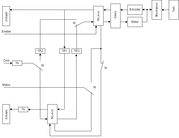
Used symbols
Symbol | Description |
|---|---|
Actuals | A common core function that contains information about the current situation of the axis. There are alternative sub-versions for the different axis types. |
TA: Tool Adaptation | A common core function that is used to handle the differences between the axis and the effective tool. |
TRx: Transformation | A core function specific to transforming axes. It is used to convert actual values of the drive side axis into load side actual values (TR1) and load side setpoints (TR2) or setpoints (TR3) into drive side values. |
MM: Operation mode select | In this figure, the “Full transformation mode” is selected. |
Semi-transformation mode
In this operation mode all commands are forwarded to the drive side axis. To avoid unexpected position lag errors, the load side axis is not enabled.
The actual position and velocity values of the load side are updated using converted values from the drive side.
Any commanded motion will be executed by the drive side using converted target position values. A commanded move to 100.0 will make the tool travel to 100.0 mm, no matter what drive side motor angle is required.
 | Velocity cannot be converted The commanded velocity cannot be converted because the result would depend on the position. |
| No constant velocity Because the profile generation is executed by the drive side axis, the tool will not move with constant velocity. |
| No position or velocity camming Position or velocity camming is not supported. |
Full transformation mode
In this operation mode, almost all commands are forwarded to the load side axis. Enabling the container object will enable both internal axes.
The actual position and velocity values of the load side are updated using converted values from the drive side.
The transformation will be performed by converting the output of the load side profile calculation. Again, a commanded move to 100.0 will make the tool travel to 100.0 mm, no matter what drive side motor angle is required.
| Constant velocity Because the profile generation is executed by the load side axis, the tool will move with constant velocity. |
| Excessive drive side velocity values required In some areas of the travel, even low tool velocities may require excessive drive side velocity values. |
| Full transformation temporarily paused For jog or homing commands, the full transformation is temporarily paused. All position and velocity values are used following drive side definitions without any conversion. |