Reactive power controller
The reactive power control is configured via the parameters of the ReactivePower group (see ReactivePower). The control is based on the requirements of the VDE and EN standards and takes into account the typical behavior of decentralized power generating plants in grid operation.
Initialization
The reactive power controller is enabled by setting bEnable = TRUE in the Control input process data (see DataAreas).
When enabled, all integrators and filters are set or reset to the current input values to ensure a stable control start.
Limiting the reactive power
The reactive power available during operation of the connected power generating plant is specified via the following parameters:
ReactiveMaxUdExt: Maximum capacitive reactive power (lower range)ReactiveMaxOvExt: Maximum inductive reactive power (upper range)
The values are to be interpreted with signs according to the generator reference arrow system.
Optionally, an active load-dependent reactive power curve of the power generating plant can be activated in order to take into account the Q(P) behavior of the plant (see chapter Reactive power control with active power characteristic curve Q(P)).
Signal filtering
The following parameters are used to filter the measured reactive power:
ActualFilterTime(Default: 10 ms)ActualFilterType(Default: PT1)
As well as the following parameters for filtering the measured voltage:
VoltageFilterTime(Default: 10 ms)VoltageFilterType(Default: PT1)
Controller structure
The reactive power controller is designed as a classic PI controller:
ControlGain: Controller gainControlIntegration: Integration time constant
Additional filtering via the following parameters is used both for smoothing and for limiting the rise of the setpoint in the direction of the controller, so that the dynamics of the controller correspond to the required behavior of a first-order filter.
ReactiveTargetFilterTime(Default: 2 s)ReactiveTargetFilterType(Default: PT1)
A first-order low-pass filter (PT1) is used for additional smoothing and limiting of the setpoint increase. As a result, the set filter time corresponds to a first-order time element with the time constant τ.
ReactiveTargetFilterTime(default: 2000 ms = 2 s = 1 τ)ReactiveTargetFilterType(default: PT1)
With the default filter time of 2 seconds (1 τ), the target value is raised to approx. 63 % of the end value. This complies with the VDE requirements to maintain a transient response over 3 τ ≈ 6 seconds.
Predictive control (optional)
If the plant characteristics are known, the delay can be taken into account based on the model. These parameters improve the transient response, particularly in plants with a dominant dead time in relation to the delay.
- PredictDeadtime: Mapping of the dead time
- PredictFilterTime: Mapping of the PT1 delay
Block diagram
The following figure shows the basic structure of the reactive power controller:
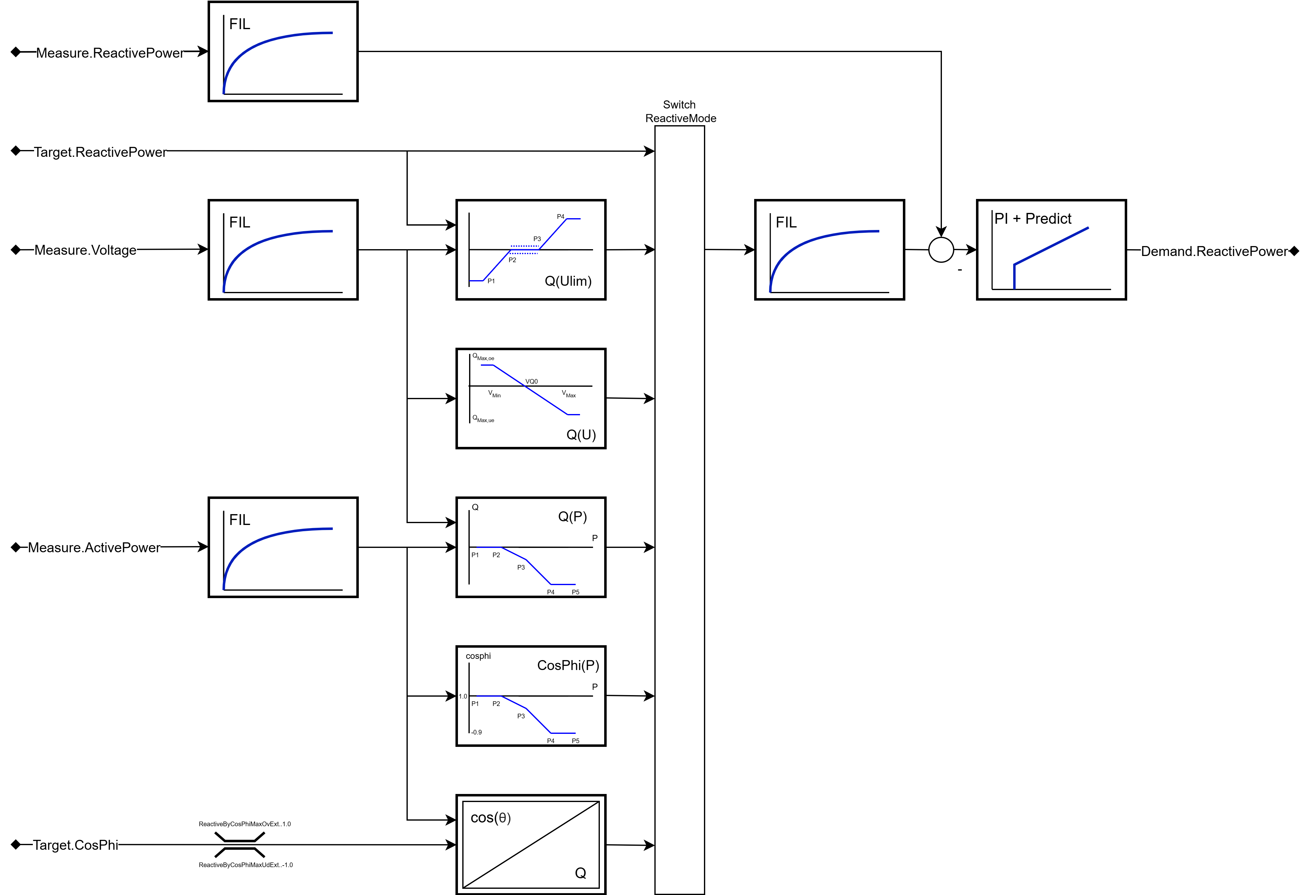
- Operation modes of the reactive power controller
- Switching operation modes during operation
- Reactive power control with constant setpoint
- Reactive power control with CosPhi displacement factor
- Reactive power control with voltage characteristic curve Q(U)
- Reactive power control with voltage limiting function Q(Ulim)
- Reactive power control with active power characteristic curve Q(P)
- Reactive power control with CosPhi(P) characteristic curve
- Active power-dependent reactive power capacity