Active power controller
The active power control of a power generating plant is configured via the parameters of the ActivePower group (see ActivePower). It adapts flexibly to the characteristics of the connected power generating units and meets the requirements of VDE and EN standards.
Initialization
The controller is enabled by setting bEnable = TRUE in the Control input process data (see DataAreas).
At startup, all integrator states and filters are adjusted or reset to the current input values to ensure a clean start of control.
Limiting the active power
The maximum available active power of the connected power generating plant (PGP) is defined in two stages:
- Static via parameters:
ActiveMaximum,ActiveMinimum - Values in [%] relative to plant output, with sign according to the generator reference arrow system.
- Dynamic via setpoint inputs (Targets):
- Two separate external setpoint inputs can be used for dynamic limitation (e.g. by grid operators or direct marketing companies).
Frequency-dependent demand response
The frequency-dependent active power control (ActiveByFrequency), which cannot be disabled, is carried out in accordance with the specifications of VDE 4110/4120 and is described in the chapter Frequency-dependent active power adjustment.
The optionally switchable primary control power (ActiveByPrimary) in accordance with VDE-AR-N 4120 is described in chapter Frequency-dependent primary control of the active power.
Signal filtering
The following parameters are used to filter the measured active power:
ActualFilterTime(Default: 10 ms)ActualFilterType(Default: PT1)
As well as the following parameters for filtering the measured frequency:
FrequencyFilterTime(Default: 10 ms)FrequencyFilterType(Default: PT1)
Controller structure
The active power controller is designed as a classic PI controller:
ControlGain: GainControlIntegration: Integration time constant
Predictive control (optional)
The typical dynamic response of a PGP according to VDE can be described by a simple PT1 behavior with characteristic values of delay time and dead time. If the actual characteristics of the plant are known, the control behavior can be improved by the following parameters.
PredictDeadtime: Mapping the dead time of the trackPredictFilterTime: Mapping of the PT1 delay
These values are taken into account by the PI controller in order to optimize the transient response - especially in systems with a significant dead time compared to the controlled system.
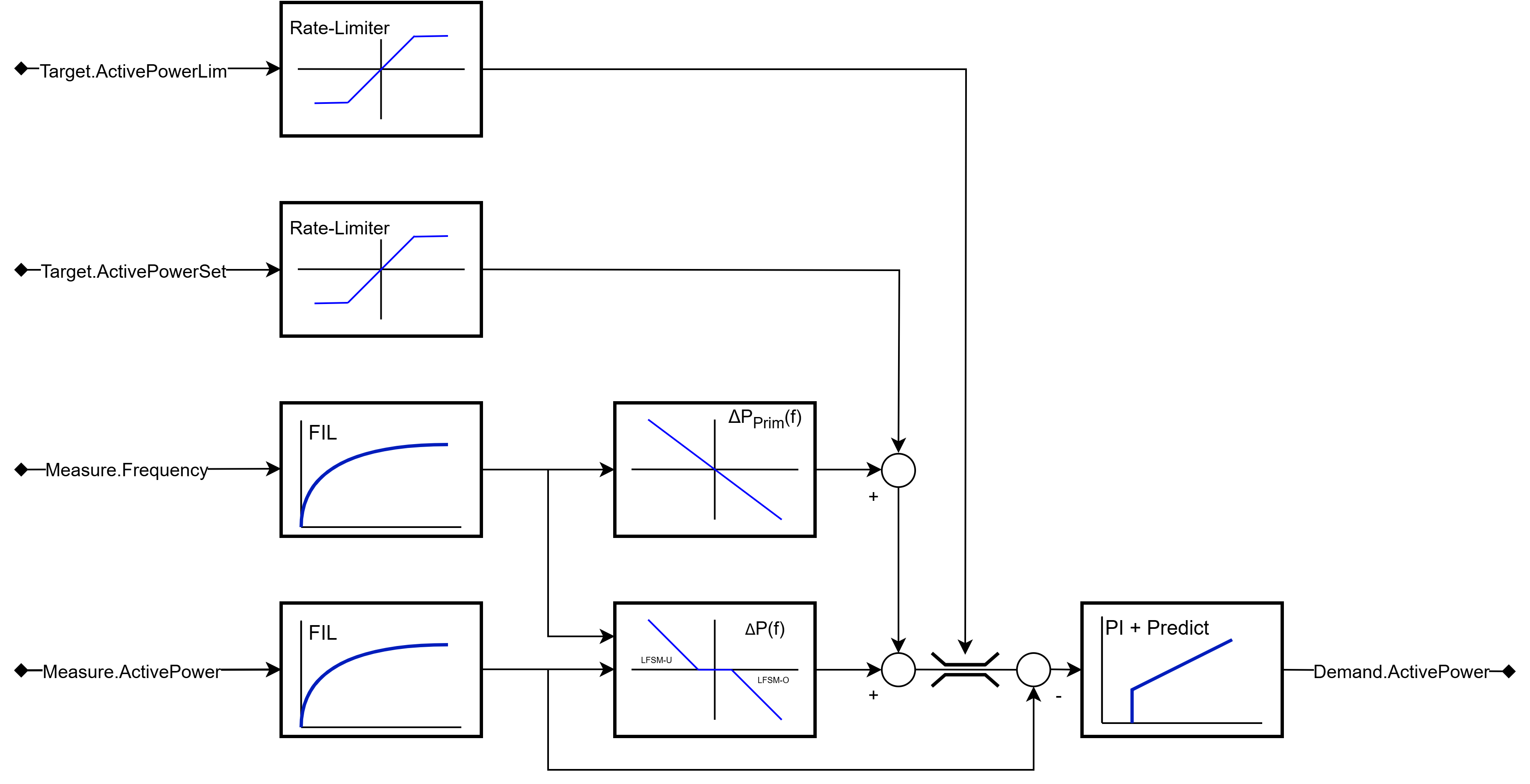
Block diagram
The following figure shows the basic structure of the active power controller: