Bandwidth management for GigE Vision
GigE Vision cameras can use up a large portion of the available transmission capacity during image transmission. However, to ensure stable operation, the network bandwidth must not be allocated entirely to image data, as sufficient capacity must be reserved for other communications.
This chapter first explains the basics of image transmission and then describes options for bandwidth management for single and multiple cameras. In addition, guidance is provided on network design and the requirements for the network components involved.
Fundamentals of image transmission
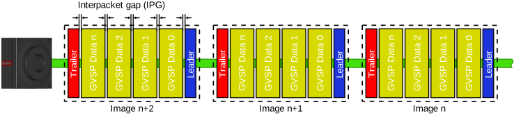
The amount of data in a camera image is usually greater than the payload that can be transmitted in a single Ethernet frame, so the data must be broken down into smaller units. With GigE Vision, the image data is divided into individual GVSP packets in accordance with the GigE Vision Stream Protocol (GVSP), and each packet is transmitted via UDP/IP within an Ethernet frame. The maximum permissible packet size is limited by the smallest Maximum Transmission Unit (MTU) along the entire transmission path. The key factors here are which Ethernet frame sizes the network components involved actually support and how they are configured. Each GVSP packet carries a portion of the image data (payload) and additional protocol information. Using this information, the application can uniquely identify the packets, put them in the correct order, and reconstruct the complete camera image from them.
To achieve the highest possible frame rates as well as low response and transmission times, a camera transmits the packets of an image in rapid succession by default. In wired Ethernet networks, the minimum gap between two Ethernet frames is defined by the Inter-Frame Gap (IFG) specified in the standard, which is 96 bit times or 12 byte times. The more general term Inter Packet Gap (IPG) is also commonly used and will be employed in the following. The actual distance between individual packets may be greater, but it never falls below the standardized IPG.
In addition to the pure transmission time, camera settings such as exposure time and trigger strategy, as well as the model-specific performance limits of the sensor and hardware, determine the time interval between two consecutive images.
Single-camera operation
The densely packed data stream described above can consume the entire available bandwidth of the transmission path during image transmission. If the data rate exceeds the transmission or processing capacity, packets may be lost. In addition to image transmission, however, the network must also handle other types of communication to ensure proper function in accordance with the GigE Vision standard:
- GVCP (GigE Vision Control Protocol): The application uses this control channel to configure and monitor the camera. This is accomplished through read and write register accesses as well as cyclic Heartbeat communication. If the control channel's feedback is delayed by image data to the point where a timeout occurs, this can lead to communication errors or even a loss of connection.
- Resend mechanism: Each GVSP packet is uniquely identified by a block ID (image block number) and a packet ID (sequential packet number). The application uses these IDs to detect a gap in the data stream. If the camera supports the resend mechanism and it is enabled in the application, the application specifically requests the missing packet again via GVCP. The camera then repeats the transmission, provided the data is still available in its internal buffer. This process places an additional load on the cable, since the retransmitted packets are added to the data stream that is already in progress. This may result in a longer wait time until the image in question is fully transferred.
Therefore, when designing the system, a sufficient bandwidth reserve must always be factored in. If the line capacity is already fully utilized by image data, GVCP responses and resend packets can no longer be transmitted in a timely manner. Each additional request increases the load even further and can therefore cause further packet loss. In the worst-case scenario, resend packets that are not transmitted in a timely manner can result in incomplete images, and delayed GVCP responses can lead to a loss of connection. To ensure stable operation, both sufficient bandwidth reserves and the processing capacity of the network components involved must be taken into account. There are essentially two approaches to this:
- Reducing the frame rate: Lowering the frame rate increases the intervals between frame transmissions, thereby creating bandwidth reserves for GVCP responses and resend packets. Since the packets for a single image are still transmitted one after another, the transmission time for that image, and thus the network-related portion of the response time, remains as short as possible. The frame rate should be set so that the transmission of a frame, including any additional communication, can be completed before the transmission of the next frame begins.
Depending on the operation mode, the frame rate is limited either directly in the camera configuration, for example, by setting a limit on theAcquisitionFrameRate, or externally via a customized trigger strategy, such as by reducing the PLC's trigger frequency. - Inserting a packet delay: To reduce short-term packet load, the GigE Vision standard provides another option via the
GevSCPD(Stream Channel Packet Delay) camera register. This register is used to insert a defined delay time between all consecutive packets in the GVSP data stream, in addition to the default IPG. This causes small gaps to appear continuously in the data stream, resulting in a longer image transmission time. The amount of data transmitted remains unchanged, but the available transmission capacity is distributed evenly across the image transmission rather than in a single block between images.
This mechanism reduces the short-term load on the network's hardware components, such as switches and network adapters, as well as on the IPC's CPU. Since the data is transmitted over an extended period of time, the network components have to process fewer packets per time interval, and the CPU has to perform fewer data copy operations. This reduces the short-term packet and CPU load and, consequently, the risk of buffer overflows.
The value forGevSCPDcan be set directly using the TcCOM parameterMinPacketDelay. The value is specified in device-specific hardware ticks. Since calculating an appropriate value is time-consuming, many cameras support theDeviceLinkThroughputLimitfeature. This allows you to specify the maximum permissible data rate directly, for example, in bytes per second or, depending on the manufacturer, as a relative percentage. The camera firmware calculates the required packet delay based on the specified data rate and automatically sets the correspondingGevSCPDvalue.

Recommendations and notes
Before limiting the frame rate or introducing a packet delay, the largest possible packet size supported by all components along the transmission path should be used. Using jumbo frames increases the proportion of payload data per Ethernet frame, while reducing the number of packets to be transmitted and the protocol overhead. The requirements and configuration are described in the Jumbo Frames chapter.
The two approaches described above serve different purposes. Reducing the frame rate frees up transmission capacity between frames, while packet delay stretches out the transmission over time, thereby reducing the short-term packet load.
If the goal is to minimize transmission and response times as much as possible, the frame rate should be limited so that there are sufficient pauses between frame transmissions. However, since the packets of an image continue to be transmitted in rapid succession, the short-term peak load during image transmission remains consistently high. If, on the other hand, the peak load on network components and the CPU needs to be reduced, the data stream can be spread out over time using packet delay. Since this increases the image transmission time, the packet delay should be set to only as long as necessary.
In both cases, the maximum sustainable frame rate may decrease immediately in the case of frame rate reduction, and as a result of the longer transmission time in the case of packet delay. These approaches can be combined as needed.
The selected settings should be verified under the maximum expected operating conditions. It is important to ensure that the data rate allocated for image data is below the stable usable data rate of the transmission path, that there is sufficient reserve capacity for additional communication, and that no packet loss or timeouts occur.
Multi-camera operation
If multiple cameras are connected via a switch to a network port on the IPC, they share a common transmission path. To ensure stable operation, the sum of the average data rates of all cameras must not exceed the transmission capacity of this shared path. The section with the highest load is the determining factor; this is typically the connection between the switch and the IPC's network port. As with single-camera operation, there must also be sufficient reserve capacity for GVCP communication and resend packets. If the required total data rate exceeds this limit, the amount of image data must be reduced, for example, by lowering the frame rate or defining a region of interest.
Beyond this bandwidth balance, the short-term peak load and the processing capacity of the components involved are critical in multi-camera operation. If multiple cameras are transmitting at the same time, packets may be lost even though the average total data rate is within the permissible range.
Calculation example: Three cameras connected to a 1 Gbit/s Port
The average image data rate of a camera can be roughly calculated as follows:
Image data rate [bytes/s] = resolution [pixels] × bytes per pixel × frame rate [fps]
Protocol overhead must also be included when determining the total network load; it is not taken into account in this simplified calculation.
For a camera with a resolution of 1920 × 1200 pixels, the Mono8 pixel format with 1 byte per pixel, and a frame rate of 30 fps, the result is:
1920 × 1200 × 1 byte × 30 fps = 69.12 MB/s
For 3 identical cameras, the total image data rate is:
3 × 69.12 MB/s = 207.36 MB/s
A 1 Gbit/s network connection has a gross data rate of 125 MB/s. Due to protocol overhead and the required reserve for GVCP communication and resend packets, this data rate is not entirely available for image data. For this example, a stable, usable image data rate of approximately 110 to 115 MB/s is assumed. The actual usable value depends on other factors, such as packet size, the network components used, and their configuration. It must therefore be tested under actual operating conditions.
The required image data rate of 207.36 MB/s significantly exceeds this target value. Therefore, operation with the selected settings is not possible via the shared 1 Gbit/s port. One possible solution is to reduce the frame rate to 15 fps:
3 × 1920 × 1200 × 1 byte × 15 fps = 103.68 MB/s
This means that, theoretically, the average image data rate is below the target value assumed for this example. However, this does not guarantee stable operation, as simultaneous transmission from multiple cameras, in particular, can cause short-term overloads.
Short-term peak load
Even if the average overall data rate falls within the stable usable data rate of the shared transmission path, short-term overloads may occur. This is especially true when multiple cameras begin transmitting their image data at the same time.
For example, if 3 cameras are each connected to a switch via a 1 Gbit/s connection, data can arrive at the switch briefly at a total rate of up to 3 Gbit/s. However, only a portion of that data can be forwarded directly via the shared 1 Gbit/s connection to the IPC. The excess packets must first be temporarily stored in the switch. If its processing or buffering capacity is insufficient for the duration of the simultaneous transmission, packets will be discarded and will subsequently be missing from the data stream.
In addition to the average bandwidth balance, it is therefore necessary to take into account the short-term peak load, the switch's buffer capacity, and the processing capacity of the entire system.
Measures to reduce peak load
To prevent short-term overloads on the switch, the data streams from the cameras must be staggered over time. A distinction can be made here between camera-side and process-side measures:
- Limiting the data stream: The packet delay described in the Single-camera operation section extends the time it takes to transmit each camera's image. As a result, fewer packets arrive at the switch per time interval, allowing it to perform continuous forwarding of the data streams over the shared connection to the IPC. The data streams may still overlap in time, but the short-term packet load and the extent of potential congestion are reduced. The requirement remains that the switch's processing and buffer capacity must be sufficient for the remaining load.
- Time separation of image transmissions: If the process allows for sufficient time intervals, the cameras can be triggered one after another. As a result, image transmissions also begin at different times, and the data streams do not overlap at the switch, or only to a very limited extent. This can reduce the required packet delay or eliminate the need for it entirely.
The time interval should be set so that the transmission of the previous image is complete before the next camera begins transmitting. In addition, an appropriate safety margin should be factored in to account for possible fluctuations in transmission time and additional communication.
If synchronized triggering is required for process-related reasons, some camera models offer aFrameTransmissionDelay. The cameras are triggered simultaneously, but begin transmitting at different times. This is merely a one-time delay in the start of transmission; the packets will then continue to be sent immediately one after the other. This merely prevents the data streams from overlapping, while the delivery of image data from cameras transmitting later is delayed accordingly. - Adjusting the network infrastructure: If the availability of transmission capacity is insufficient to handle the required total data rate, or if short-term peak loads cannot be reliably managed, the network infrastructure must be adjusted. Possible solutions include a switch with sufficient processing power and sufficiently large packet buffers, a faster connection between the switch and the IPC, or distributing the cameras across multiple network ports. Larger packet buffers can absorb short-term overloads, but they cannot compensate for a sustained exceeding of transmission capacity. These measures do not affect the amount of data generated. Depending on the measure, the buffer reserve is increased, the available transmission or processing capacity is expanded, or the load is distributed across multiple transmission paths.
To ensure stable multi-camera operation, both the bandwidth balance and short-term peak load must be taken into account. The methods described can be combined as needed. The selected system configuration should be tested for packet loss and timeouts under the most extreme operating conditions expected.