Getting started
This documentation article is intended to allow you an initial, quick start in how to use this product. Following successful installation and licensing, perform the following steps in order to establish a connection to an S7 controller and configure variables for the read/write access.
Add an S7 Communication I/O device
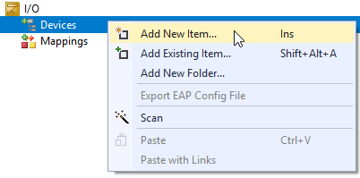
- 1. As the TwinCAT S7 Communication product is based on the real-time Ethernet adapter, you first add a real-time Ethernet adapter (Multi Protocol Handler) as an I/O device to your TwinCAT configuration. To do so, select Add New Item..
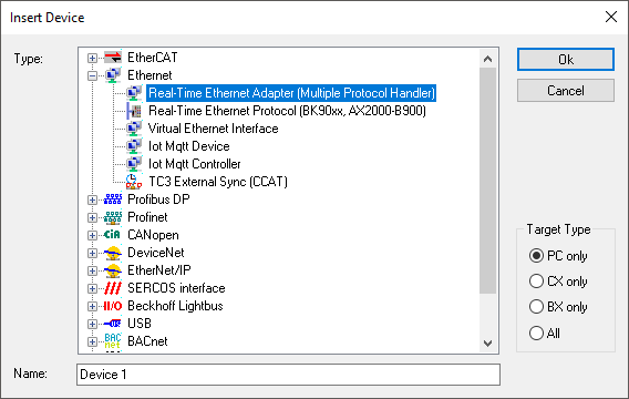
- 2. In the Insert Device dialog you confirm the selection Real-Time Ethernet Adapter (Multi Protocol Handler) with OK
- 3. You then link this adapter with the network interface card correspondingly configured for this.
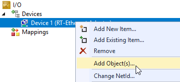
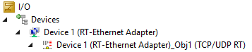
- 4. In the next step you add a TCP/UDP RT module below the real-time Ethernet adapter. To do so, select Add Object(s)..
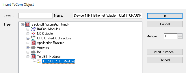
- 5. Confirm the TCP/UDP RT Module selection with OK.
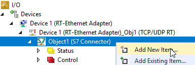
- 6. Then you add an S7 Connector to the TCP/UDP RT module. Several S7 Connectors can be added. For this purpose, also bear in mind the instructions about any possible Technical Restrictions.
To do so, select Add New Item…
again.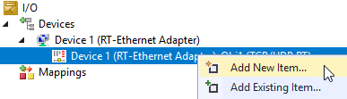
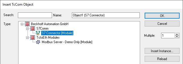
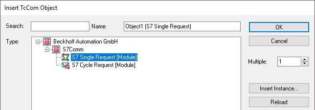
- 7. In the dialog that opens, press OK to add the S7 Connector (Module).
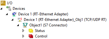
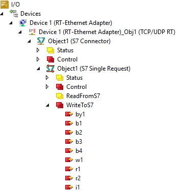
- The finished I/O configuration should then look like this:
Configuring the connection parameters
Once you have added the I/O device, you can define the connection parameters for the Siemens S7 Controller on the S7 Connector.
- 1. To do so, double click on the S7 Connector.
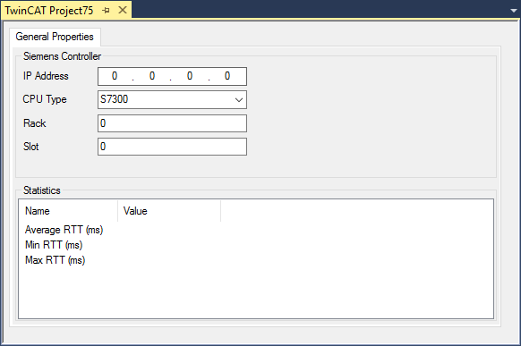
- The following connection parameters must be configured for the Siemens S7 Controller:
Parameter | Description |
|---|---|
IP Address | IP address of the Siemens S7 Controller |
CPU Type | Type of Siemens S7 Controller |
Rack | Rack ID, see S7 view of the device |
Slot | Slot ID, see S7 view of the device |
Access to data points via the process image
Normally, data points on the S7 Controller are accessed via the process image, i.e. the data points should be able to be linked as variables in the process image with other variables, e.g. from the PLC. For this purpose, two different types of access can be configured on the S7 Connector: SingleRequest and CyclicRequest.
Access types
With SingleRequest, the configured data points are only read or written “on demand”. For this, corresponding trigger variables are available in the process image. With CyclicRequest, the corresponding data points are read/written cyclically during a configurable cycle time. Both access types are described in detail once again in a separate document article about SingleRequest vs. CyclicRequest.
Data point configuration
After selecting an access type, the data points can be configured. This is done using the appropriate tabs, Read Variables or Write Variables, for the S7 Request object.
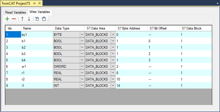
In this tabular overview, the address information of a data point can be configured on the S7 Controller. These include: Name of the variables (only for display in the process image), Data Type, S7 Data Area, S7 Byte Address, S7 Bit Offset, S7 Data Block. This information is provided by the Siemens S7 Controller.
You can also import the data points from a file or export already configured data points. This makes it easier to exchange this information with other tools. Further information can be found in the documentation article Importing and exporting data points.
The configured data points below the Read Variables tab are added in the process image to the ReadFromS7 node as input variables and from there can now be linked with other variables.
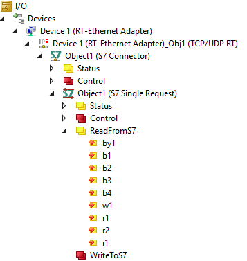
The configured data points below the Write Variables tab are added in the process image to the WriteToS7 node as output variables and from there can now be linked with other variables.
Access to data points via the PLC
Alternatively, the data points can also be configured from the PLC program and be read or written using a function block. For this purpose, the PLC library Tc3_S7Comm is available. Unlike the configuration of data points via the process image, with this version, no access type has to be specified as access takes place directly from the PLC logic. The connection parameters are also configured from the PLC. Therefore you do not have to add an S7 Connector for this version.
Using the PLC library already mentioned above and the function blocks contained therein, you then have the option of configuring this information.
Sample:
fbConnection: FB_S7CommConnection(16#01010050);
fbRequestRead: FB_S7CommSingleRequest;

fbConnection.sIpAddr := '10.3.32.101';
fbConnection.eCpuType := E_S7COMM_CPUTYPE.S71500;
fbConnection.nRack := 0;
fbConnection.nSlot := 0;

fbRequestRead.AddReadVar(ADR(data_byte), SIZEOF(data_byte), 0, E_S7COMM_DATAAREA.DATA_BLOCKS, 1);
fbRequestRead.AddReadVar(ADR(data_dword), SIZEOF(data_dword), 2, E_S7COMM_DATAAREA.DATA_BLOCKS, 1);
Further information about both types of communication can be found in the document article Mapping vs. PLC library, as well as in the Samples.
Notice | |
Constructor parameter at FB_S7CommConnection Please make sure that the constructor parameter of the "FB_S7CommConnection" function block is configured with the object ID of your TCPUDP stack. These can be found on the "Objects" tab of the TCPUDP RT adapter in your I/O settings. |
 | FB_S7CommConnection The FB_S7CommConnection function block is initialized with the ID of the TCP/UDP RT module. This can either, as shown in the code snippet above, be entered statically or configured in the properties of the PLC project instance via the initialization symbol. The latter is shown in the Samples. |