SV Publisher/Subscriber according to UCA 61850-9-2 Light Edition - Transmission of sampled measured values
This example shows the TwinCAT IEC 61850 implementation of the transmission of sampled digitized measured values using SV messages (Sampled Value Messages) according to UCA (Utility Communications Architecture) 61850-9-2LE (Light Edition) [1].
The Light Edition (9-2LE) is not a standard, but a technical implementation guide for digital data exchange. This guideline is intended to ensure interoperability between devices from different manufacturers and defines a subset of the IEC 61850-9-2 standard. The implementation of this subset should contribute to a faster market launch of the standard.
System requirement
TwinCAT TF6510 IEC 61850 Telecontrol v3.3.99.0 or higher.
Download TwinCAT XAE Project (*.zip): Sample14.zip
References
[1] IEC 61850-9-2LE (Light Edition) Implementation Guideline for Digital Interface to Instrument Transformers using IEC 61850-9-2, UCA International Users Group, www.ucaiug.org.
General information about this sample project
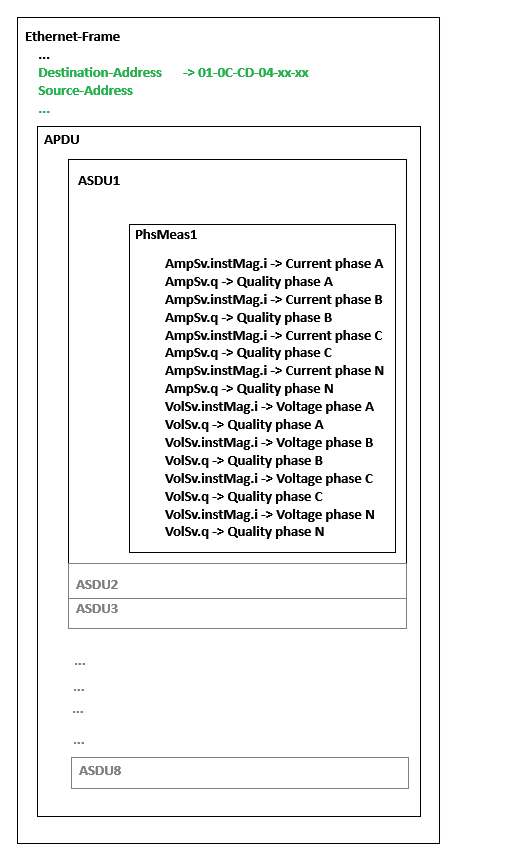
The 9-2LE is a UCA profile in which the data set (ASDU) of the SV message (APDU) is limited to a maximum of 4 voltage values and 4 current values (4 currents and 4 voltages of phase A, B, C and the neutral conductor (N)). Each ASDU contains the 4 three-phase current and voltage measurement values. An SV message (APDU) can contain either 1 or 8 data records (ASDUs). The quality information is also transmitted in the ASDU for each measured current and voltage value. The figure below shows a simplified representation of the SV message within an Ethernet frame.
The sample consists of two separate TwinCAT IEC 61850 projects. After unpacking the zip archive, you will find a TwinCAT IEC 61850 Server (SV Publisher) in the subfolder |Sample14|Publisher and a TwinCAT IEC 61850 Client (SV Subscriber) project in the subfolder |Sample14|Subscriber. Both projects are coordinated with each other.
The IP address of the server must be adapted in the code of both projects. The client will establish a connection to the server when you download, activate and start the projects on two TwinCAT target systems connected via LAN. However, the configuration of the IP address and the existence of the client-server connection are not mandatory for SV transmission. SV communication takes place using a publisher-subscriber model. The SV communication stack is mapped directly to the data link layer (layer 2) for maximum speed.
In the project tree under the I/O-Device branch you will find a network adapter instance named "GSE (RT Ethernet adapter)". This adapter instance must be configured accordingly, i.e. the I/O configuration must be adapted to the existing hardware and to the target platform on which the project is to run. A new I/O configuration is also necessary if you change the target platform. This configuration must be done manually in TwinCAT XAE. In addition to the I/O configuration of the network adapter, a link must be established between the network adapter and the PLC function blocks for SV communication. This link allows SV messages received by the network adapter to be forwarded to the instance of the SV Subscriber function block. In the opposite direction, the instance of the SV Publisher function block can forward the SV messages to be sent to the network adapter. You can find more information on the topic here: RT Ethernet adapter Configuration.
The data model of the merging unit
According to 9-2LE, the data model requires 4 instances of the logical node: TCTR (current transformer) and 4 instances of the logical node: TVTR (voltage transformer). The sample project contains the following LNs:
Logical node | Type | Description |
|---|---|---|
InnATCTR1 | TCTR | Current transformer, phase A |
InnBTCTR2 | TCTR | Current transformer, phase B |
InnCTCTR3 | TCTR | Current transformer, phase C |
InnNTCTR4 | TCTR | Current transformer, neutral conductor N |
UnnATVTR1 | TVTR | Voltage transformer, phase A |
UnnBTVTR2 | TVTR | Voltage transformer, phase B |
UnnCTVTR3 | TVTR | Voltage transformer, phase C |
UnnNTVTR4 | TVTR | Voltage transformer, neutral conductor N |
The 9-2LE guide defines the data set: "PhsMeas1". This data set fixes which attributes from the data model are transferred as sampled values in the ASDU and then in the SV message (APDU).
PhsMeas1 Dataset member | CDC | FC |
|---|---|---|
InnATCTR1.AmpSv | SAV | MX |
InnBTCTR2.AmpSv | SAV | MX |
InnCTCTR3.AmpSv | SAV | MX |
InnNTCTR4.AmpSv | SAV | MX |
InnATVTR1.VolSv | SAV | MX |
InnBTVTR2.VolSv | SAV | MX |
InnCTVTR3.VolSv | SAV | MX |
InnNTVTR4.VolSv | SAV | MX |
The dataset members: "AmpSv" and "VolSv" should have the following mandatory attributes:
Attribute | Type | Description |
|---|---|---|
instMag.i | INT32 | Sampled measured value (voltage or current) |
q | Quality | Quality flags including the additional Derived flag. |
The guide also defines scaling factors for current and voltage. The current and voltage values must be scaled with the respective factor and transmitted as whole numbers. Current factor: 1000 (LSB: 1 mA). Voltage factor: 100 (LSB: 10 mV).
SV control blocks
The 9-2LE document defines two SV control blocks: "MSVCB01" (80 samples per period) and "MSVCB02" (256 samples per period). At least one of these blocks must be implemented. With "MSVCB01" only one ASDU is transmitted in an SV message and with "MSVCB02" eight ASDUs. The sample project implements both control blocks. The control block instances can be found in the LLN0 node.
MSVCB01: FB_GseMsvCBImplClass := (MsvID:=(sValue:='xxxxMUnn01'), DatSet:=(sValue:='IEDMUnn/LLN0.PhsMeas1'), ConfRev:=(nValue:=1), SmpRate:=(nValue:=80), OptFlds:=(RefreshTime:=TRUE), DstAddress:=(sAddr:='01-0C-CD-04-00-00', nPRIORITY:=4, nVID:=16#000, nAPPID:=16#4000), NoASDU:=(nValue:=1), bLinkResult:=THIS^.AddMulticastSampledValueControlBlockToContainer(ipMulticastSampledValueControlBlock:=MSVCB01));
MSVCB02: FB_GseMsvCBImplClass := (MsvID:=(sValue:='xxxxMUnn02'), DatSet:=(sValue:='IEDMUnn/LLN0.PhsMeas1'), ConfRev:=(nValue:=1), SmpRate:=(nValue:=256), OptFlds:=(RefreshTime:=TRUE), DstAddress:=(sAddr:='01-0C-CD-04-00-01', nPRIORITY:=4, nVID:=16#000, nAPPID:=16#4001), NoASDU:=(nValue:=8), bLinkResult:=THIS^.AddMulticastSampledValueControlBlockToContainer(ipMulticastSampledValueControlBlock:=MSVCB02));Theoretically, each SV message (APDU) can combine up to 8 ASDUs from different sources. In this case, each ASDU is identified by its unique identifier ("MsvID"). The guide recommends the use of an APPID ("nAPPID") with the value: 0x4000 and the use of multicast addresses ("DstAddress") from the value range: "01:0C:CD:04:xx:xx". The configuration version ("ConfRev") should always have the value: 1.
The SV Subscriber only receives, filters and analyzes messages that are assigned to the respective subscriber.
SV task configuration
The SV messages are processed by two separate PLC tasks in the sample project. Task: "PlcTaskSV01" processes the data of the control block: "MSVCB01" and Task: "PlcTaskSV02" processes the data of the control block: "MSVCB02".
The control blocks send the SV messages at precisely defined time intervals t. The time interval t. depends on the frequency of the measuring signal (mains frequency) and the number of samples per period (SPP).
Calculation of the time interval for "MSVCB01":
Mains frequency f: 50 Hz and SPP: 80
t = 1/(f*SPP) = 1/(50*80) = 0.00025 s = 250 µs
In this case, an SV message (APDU with an ASDU) is sent every 250 µs. This means a total of 4000 frames/second.
Calculation of the time interval for "MSVCB02":
Mains frequency f: 50 Hz and SPP: 256
t = 1/(f*SPP) = 1/(50*256) = 0.000078125 s = 78.125 µs
In this case, however, an SV message is only sent every 625 µs because each SV message contains 8 ASDUs (the measured values in the ASDUs have the same sources). This means a total of 1600 frames/second.
In the sample, the TwinCAT base time for all PLC tasks is preconfigured to the value: 125 µs. This enables us to simulate the SV transmission of the sampled values of the three-phase voltages/currents in the 50 Hz grid. The "Cycle ticks" multiplier of the PLC task: "PlcTaskSV01" has the value: 2 and it is therefore called every 250 µs. The "Cycle tics" multiplier of the PLC task: "PlcTaskSV02" has the value: 5 and it is therefore called every 625 µs. This corresponds to the 9-2LE requirement for "MSVCB01" and "MSVCB02" in order to fulfill the SPP values 80 and 256 respectively (50 Hz mains frequency). Each control block periodically sends exactly one SV message in its own task cycle.
The PLC task: "PlcTask" with a cycle time of 10 ms is responsible for processing the client-server communication.
Special SV data structures and SV function blocks
In addition to the IED data model, the TwinCAT Telecontrol Configurator also generates the structured data types and function blocks required for SV implementation. The SV data structures are saved in the project tree: "\DUTs\{IEDName}\Sampled Values" and the SV function blocks are saved in the project tree: "\POUs\{IEDName}\Sampled Values". The structured data types and function blocks are required to convert the sampled measured values, which are initially available in TwinCAT PLC data format (SV Publisher), into the data format that is to be transmitted in the SV message. In the opposite direction, the data received in the SV message is converted into the TwinCAT PLC data format (SV Subscriber). The IEC 61850-9-2 standard defines special encoding rules for the IEC 61850-7-2 basic types. In principle, only simple basic types are coded in the SV message. This means that even with the constructed data types (CDCs): "VolSv" and "AmpSv" in the data set: "PhsMeas1", only the data of the attributes "i" and "q" are coded in the SV message. The generated SV data structures and SV function blocks are briefly described below. For the sake of simplicity, this is only done using the "MSVCB01" control block implementation as an example.
The generated SV data structures have the following name prefixes: "ST_SVDATA_", "ST_SVASDU_", "ST_SVAPDU_" and "ST_SVBUFFER_" (only in the SV Subscriber project).
The type encoding, byte alignment and byte order of the member variables in the data structure: "ST_SVDATA_IED_MUnn_LLN0_PhsMeas1" corresponds exactly to the structure of the data from the data record: "PhsMeas1" and the format in which this data record is transmitted in the network. This means that the data in this structure has 1-byte alignment and network byte order (big-endian). The data types are already converted to SV data types according to the encoding rules from the IEC 61850-7-2 standard.
(* SV dataset values buffer type (IEC 61850 big endian network byte order) *)
{attribute 'pack_mode' := '1'}
TYPE ST_SVDATA_IED_MUnn_LLN0_PhsMeas1 :
STRUCT
    IED_MUnn_InnATCTR1_AmpSv_instMag_i: T_OCTET4;
    IED_MUnn_InnATCTR1_AmpSv_q: T_OCTET4;
    IED_MUnn_InnBTCTR2_AmpSv_instMag_i: T_OCTET4;
    IED_MUnn_InnBTCTR2_AmpSv_q: T_OCTET4;
    IED_MUnn_InnCTCTR3_AmpSv_instMag_i: T_OCTET4;
    IED_MUnn_InnCTCTR3_AmpSv_q: T_OCTET4;
    IED_MUnn_InnNTCTR4_AmpSv_instMag_i: T_OCTET4;
    IED_MUnn_InnNTCTR4_AmpSv_q: T_OCTET4;
    IED_MUnn_UnnATVTR1_VolSv_instMag_i: T_OCTET4;
    IED_MUnn_UnnATVTR1_VolSv_q: T_OCTET4;
    IED_MUnn_UnnBTVTR2_VolSv_instMag_i: T_OCTET4;
    IED_MUnn_UnnBTVTR2_VolSv_q: T_OCTET4;
    IED_MUnn_UnnCTVTR3_VolSv_instMag_i: T_OCTET4;
    IED_MUnn_UnnCTVTR3_VolSv_q: T_OCTET4;
    IED_MUnn_UnnNTVTR4_VolSv_instMag_i: T_OCTET4;
    IED_MUnn_UnnNTVTR4_VolSv_q: T_OCTET4;
END_STRUCT
END_TYPE
The member variables in data structure: "ST_SVASDU_IED_MUnn_LLN0_MSVCB01" have the encoding type, the byte alignment and the byte order, which correspond to the type, alignment and byte order of the data in TwinCAT PLC or the TwinCAT IEC 61850 data format. This means that the data in this structure has 8-byte alignment and host byte order (little-endian). In addition to some additional variables such as: "nSmpCnt" (sample counter), "eSmpSynch" (synchronization type) and "tRefrTm" (refresh timestamp), the remaining member variables correspond to the structure of the data in the data set: "PhsMeas1".
(* SV ASDU data type (TwinCAT PLC little endian host byte order) *)
TYPE ST_SVASDU_IED_MUnn_LLN0_MSVCB01 :
STRUCT
    nSmpCnt: UINT; (* Sample counter *)
    eSmpSynch: E_GseSvSmpSynch; (* Synchronization type: 0..2 *)
    tRefrTm: T_UtcTime; (* Sample refresh time stamp (optional) *)

    IED_MUnn_InnATCTR1_AmpSv_instMag_i: DINT;
    IED_MUnn_InnATCTR1_AmpSv_q: ST_AcsiQuality;
    IED_MUnn_InnBTCTR2_AmpSv_instMag_i: DINT;
    IED_MUnn_InnBTCTR2_AmpSv_q: ST_AcsiQuality;
    IED_MUnn_InnCTCTR3_AmpSv_instMag_i: DINT;
    IED_MUnn_InnCTCTR3_AmpSv_q: ST_AcsiQuality;
    IED_MUnn_InnNTCTR4_AmpSv_instMag_i: DINT;
    IED_MUnn_InnNTCTR4_AmpSv_q: ST_AcsiQuality;
    IED_MUnn_UnnATVTR1_VolSv_instMag_i: DINT;
    IED_MUnn_UnnATVTR1_VolSv_q: ST_AcsiQuality;
    IED_MUnn_UnnBTVTR2_VolSv_instMag_i: DINT;
    IED_MUnn_UnnBTVTR2_VolSv_q: ST_AcsiQuality;
    IED_MUnn_UnnCTVTR3_VolSv_instMag_i: DINT;
    IED_MUnn_UnnCTVTR3_VolSv_q: ST_AcsiQuality;
    IED_MUnn_UnnNTVTR4_VolSv_instMag_i: DINT;
    IED_MUnn_UnnNTVTR4_VolSv_q: ST_AcsiQuality;
END_STRUCT
END_TYPE
The member variables in the data structure: "ST_SVAPDU_IED_MUnn_LLN0_MSVCB01" are instances of the "ST_SVASDU_" data structure in TwinCAT PLC data format (little-endian, host byte order).
(* SV APDU data type (TwinCAT PLC little endian host byte order) *)
TYPE ST_SVAPDU_IED_MUnn_LLN0_MSVCB01 :
STRUCT
    Asdu1: ST_SVASDU_IED_MUnn_LLN0_MSVCB01; (* SV ASDU *)
END_STRUCT
END_TYPE
Type encoding and data mapping
The function blocks with the name prefix: "FB_SVTXASDU_", "FB_SVTXAPDU_", "FB_SVRXASDU_" and "FB_SVRXAPDU_" are responsible for the type encoding and mapping of the data. Each time the "Update()" method is called in the SV Publisher (further information on this can be found further down in this documentation), the method: "OnSvPublisherHostToNet()" is called in the function block: "FB_SVTXAPDU_IED_MUnn_LLN0_MSVCB01". In this method, the data is converted from TwinCAT PLC host format to SV network format before it is sent as an SV message.
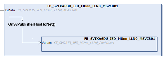
To perform the conversion, the implementation code of the method: "OnSvPublisherHostToNet()" uses methods that are already implemented in the base class: "FB_GseSvApduClass" (see sample below).
(* Converts SV publisher data to be sent from host (little-endian) to network (big-endian) byte order *)
METHOD FINAL OnSvPublisherHostToNet
VAR_INPUT
    ipAdapter: I_GseAdapterClass; (* Network adapter interface pointer *)
    ipApdu: I_GseSvApduClass; (* APDU object interface pointer *)
END_VAR
Asdu1.nSmpCnt:= TxData.Asdu1.nSmpCnt; (* Set sample counter *)
Asdu1.eSmpSynch:= TxData.Asdu1.eSmpSynch; (* Set synchronization type: 0..2 *)
Asdu1.tRefrTm:= TxData.Asdu1.tRefrTm; (* Set refresh time stamp (optional) *)
(* Convert SV data to be sent from host byte order to network byte order *)
HostToNetInt32(in:=TxData.Asdu1.IED_MUnn_InnATCTR1_AmpSv_instMag_i, out:=Asdu1.Values.IED_MUnn_InnATCTR1_AmpSv_instMag_i);
HostToNetQuality(in:=TxData.Asdu1.IED_MUnn_InnATCTR1_AmpSv_q, out:=Asdu1.Values.IED_MUnn_InnATCTR1_AmpSv_q);
HostToNetInt32(in:=TxData.Asdu1.IED_MUnn_InnBTCTR2_AmpSv_instMag_i, out:=Asdu1.Values.IED_MUnn_InnBTCTR2_AmpSv_instMag_i);
HostToNetQuality(in:=TxData.Asdu1.IED_MUnn_InnBTCTR2_AmpSv_q, out:=Asdu1.Values.IED_MUnn_InnBTCTR2_AmpSv_q);
HostToNetInt32(in:=TxData.Asdu1.IED_MUnn_InnCTCTR3_AmpSv_instMag_i, out:=Asdu1.Values.IED_MUnn_InnCTCTR3_AmpSv_instMag_i);
HostToNetQuality(in:=TxData.Asdu1.IED_MUnn_InnCTCTR3_AmpSv_q, out:=Asdu1.Values.IED_MUnn_InnCTCTR3_AmpSv_q);
HostToNetInt32(in:=TxData.Asdu1.IED_MUnn_InnNTCTR4_AmpSv_instMag_i, out:=Asdu1.Values.IED_MUnn_InnNTCTR4_AmpSv_instMag_i);
HostToNetQuality(in:=TxData.Asdu1.IED_MUnn_InnNTCTR4_AmpSv_q, out:=Asdu1.Values.IED_MUnn_InnNTCTR4_AmpSv_q);
HostToNetInt32(in:=TxData.Asdu1.IED_MUnn_UnnATVTR1_VolSv_instMag_i, out:=Asdu1.Values.IED_MUnn_UnnATVTR1_VolSv_instMag_i);
HostToNetQuality(in:=TxData.Asdu1.IED_MUnn_UnnATVTR1_VolSv_q, out:=Asdu1.Values.IED_MUnn_UnnATVTR1_VolSv_q);
HostToNetInt32(in:=TxData.Asdu1.IED_MUnn_UnnBTVTR2_VolSv_instMag_i, out:=Asdu1.Values.IED_MUnn_UnnBTVTR2_VolSv_instMag_i);
HostToNetQuality(in:=TxData.Asdu1.IED_MUnn_UnnBTVTR2_VolSv_q, out:=Asdu1.Values.IED_MUnn_UnnBTVTR2_VolSv_q);
HostToNetInt32(in:=TxData.Asdu1.IED_MUnn_UnnCTVTR3_VolSv_instMag_i, out:=Asdu1.Values.IED_MUnn_UnnCTVTR3_VolSv_instMag_i);
HostToNetQuality(in:=TxData.Asdu1.IED_MUnn_UnnCTVTR3_VolSv_q, out:=Asdu1.Values.IED_MUnn_UnnCTVTR3_VolSv_q);
HostToNetInt32(in:=TxData.Asdu1.IED_MUnn_UnnNTVTR4_VolSv_instMag_i, out:=Asdu1.Values.IED_MUnn_UnnNTVTR4_VolSv_instMag_i);
HostToNetQuality(in:=TxData.Asdu1.IED_MUnn_UnnNTVTR4_VolSv_q, out:=Asdu1.Values.IED_MUnn_UnnNTVTR4_VolSv_q);Each time the SV Subscriber receives a new SV message, the method: "OnSvSubscriberNetToHost()" is called in the function block: "FB_SVRXAPDU_IED_MUnn_LLN0_MSVCB01". In this method, the received data is converted from the SV network format to the TwinCAT PLC host or TwinCAT IEC 61850 data format. After the conversion, the event method: "OnSvUpdate()" is called in the SV Subscriber (further information on this can be found further down in this documentation).
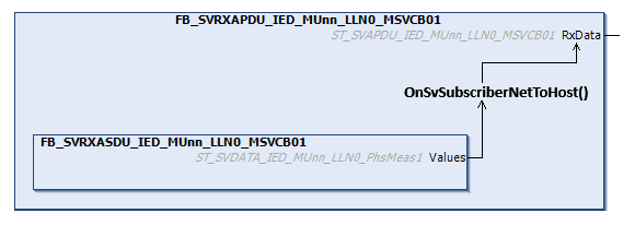
To perform the conversion, the implementation code of the method: "OnSvSubscriberNetToHost()" uses methods that are already implemented in the base class: "FB_GseSvApduClass" (see sample code below).
(* Converts received SV subscriber data from network (big-endian) to host (little-endian) byte order *)
METHOD FINAL OnSvSubscriberNetToHost
VAR_INPUT
    ipAdapter: I_GseAdapterClass; (* Network adapter interface pointer *)
    ipApdu: I_GseSvApduClass; (* APDU object interface pointer *)
END_VAR
RxData.Asdu1.nSmpCnt:= Asdu1.nSmpCnt; (* Get sample counter *)
RxData.Asdu1.eSmpSynch:= Asdu1.eSmpSynch; (* Get synchronization type: 0..2 *)
RxData.Asdu1.tRefrTm:= Asdu1.tRefrTm; (* Get refresh time stamp (optional) *)
(* Convert received SV data from network byte order to host byte order *)
NetToHostInt32(in:=Asdu1.Values.IED_MUnn_InnATCTR1_AmpSv_instMag_i, out:=RxData.Asdu1.IED_MUnn_InnATCTR1_AmpSv_instMag_i);
NetToHostQuality(in:=Asdu1.Values.IED_MUnn_InnATCTR1_AmpSv_q, out:=RxData.Asdu1.IED_MUnn_InnATCTR1_AmpSv_q);
NetToHostInt32(in:=Asdu1.Values.IED_MUnn_InnBTCTR2_AmpSv_instMag_i, out:=RxData.Asdu1.IED_MUnn_InnBTCTR2_AmpSv_instMag_i);
NetToHostQuality(in:=Asdu1.Values.IED_MUnn_InnBTCTR2_AmpSv_q, out:=RxData.Asdu1.IED_MUnn_InnBTCTR2_AmpSv_q);
NetToHostInt32(in:=Asdu1.Values.IED_MUnn_InnCTCTR3_AmpSv_instMag_i, out:=RxData.Asdu1.IED_MUnn_InnCTCTR3_AmpSv_instMag_i);
NetToHostQuality(in:=Asdu1.Values.IED_MUnn_InnCTCTR3_AmpSv_q, out:=RxData.Asdu1.IED_MUnn_InnCTCTR3_AmpSv_q);
NetToHostInt32(in:=Asdu1.Values.IED_MUnn_InnNTCTR4_AmpSv_instMag_i, out:=RxData.Asdu1.IED_MUnn_InnNTCTR4_AmpSv_instMag_i);
NetToHostQuality(in:=Asdu1.Values.IED_MUnn_InnNTCTR4_AmpSv_q, out:=RxData.Asdu1.IED_MUnn_InnNTCTR4_AmpSv_q);
NetToHostInt32(in:=Asdu1.Values.IED_MUnn_UnnATVTR1_VolSv_instMag_i, out:=RxData.Asdu1.IED_MUnn_UnnATVTR1_VolSv_instMag_i);
NetToHostQuality(in:=Asdu1.Values.IED_MUnn_UnnATVTR1_VolSv_q, out:=RxData.Asdu1.IED_MUnn_UnnATVTR1_VolSv_q);
NetToHostInt32(in:=Asdu1.Values.IED_MUnn_UnnBTVTR2_VolSv_instMag_i, out:=RxData.Asdu1.IED_MUnn_UnnBTVTR2_VolSv_instMag_i);
NetToHostQuality(in:=Asdu1.Values.IED_MUnn_UnnBTVTR2_VolSv_q, out:=RxData.Asdu1.IED_MUnn_UnnBTVTR2_VolSv_q);
NetToHostInt32(in:=Asdu1.Values.IED_MUnn_UnnCTVTR3_VolSv_instMag_i, out:=RxData.Asdu1.IED_MUnn_UnnCTVTR3_VolSv_instMag_i);
NetToHostQuality(in:=Asdu1.Values.IED_MUnn_UnnCTVTR3_VolSv_q, out:=RxData.Asdu1.IED_MUnn_UnnCTVTR3_VolSv_q);
NetToHostInt32(in:=Asdu1.Values.IED_MUnn_UnnNTVTR4_VolSv_instMag_i, out:=RxData.Asdu1.IED_MUnn_UnnNTVTR4_VolSv_instMag_i);
NetToHostQuality(in:=Asdu1.Values.IED_MUnn_UnnNTVTR4_VolSv_q, out:=RxData.Asdu1.IED_MUnn_UnnNTVTR4_VolSv_q);SV Publisher function block
In the global variable list: TcTelecontrol you will find an IED data model function block instance: "fbIED" and two SV Publisher function block instances. The program: "P_IEC61850SV01" is called by "PlcTaskSV01". "P_IEC61850SV01" in turn calls the SV Publisher function block: "fbIED_MUnn_MSVCB01SvPublisher", which is responsible for sending the SV messages. The second SV Publisher function block: "fbIED_MUnn_MSVCB02SvPublisher" is called by "PlcTaskSV02" and the program: "P_IEC61850SV02".
VAR_GLOBAL
    …
    (* IED data model *)
    fbIED: FB_IED_IED;
    (* Sampled values publisher *)
    fbIED_MUnn_MSVCB01SvPublisher: FB_IED_MUnn_MSVCB01SvPublisher := (fbAdapter:=(ipIED:=fbIED, settings:=(eDispatchMode:=E_GseDispatchMode.NonPromiscuous)));
    fbIED_MUnn_MSVCB02SvPublisher: FB_IED_MUnn_MSVCB02SvPublisher := (fbAdapter:=(ipIED:=fbIED, settings:=(eDispatchMode:=E_GseDispatchMode.NonPromiscuous)));
    …
END_VAR
In the sample implementation, the SV publishing process is started automatically for both SV control blocks after the PLC is started. A rising edge at the "bStop" variable stops the Publishing process. Simulated current and voltage measured values are generated by the "FB_GseSvPhsMeasGeneratorClass" function block for SV transmission. If the SV transmission was started via a rising edge at the "bStart" variable (this happens automatically after the PLC is started) and the "bUpdate" variable has the value TRUE, new measured values for the current and voltage of the three phases A, B and C are generated in the method: SvSimulation() and assigned to "fbApdu1.TxData". The current and voltage values of the neutral conductor (N) are calculated from the sum of the measured values of phases A, B and C. See the sample code implementation of the MSVCB01 publisher below.
(* Sampled values publisher *)
FUNCTION_BLOCK FB_IED_MUnn_MSVCB01SvPublisher IMPLEMENTS I_GseLinkStatusEventSink
VAR_INPUT
    fbAdapter: FB_GseAdapterClass := (ipLinkStatus:=THIS^); (* GSE network adapter *)
    fbApdu1: FB_SVTXAPDU_IED_MUnn_LLN0_MSVCB01; (* SV publisher APDU *)
END_VAR
VAR
    eLinkStatus: E_GseLinkStatus; (* Network adapter link status *)
    bSuccess: BOOL;
    ipError: I_ServiceErrorClass;
    bStart: BOOL := TRUE; (* Rising edge starts publishing of SV data *)
    bStop: BOOL; (* Rising edge stops publishing of SV data *)
    bUpdate: BOOL := TRUE; (* Enable/disable cyclic update of published SV data. Default: TRUE (enabled) *)
    bUpdateOnce: BOOL; (* Rising edge updates published SV data only once *)

    bSynch: BOOL := TRUE; (* Rising edge at this input resets the sample counter to 0 *)
    nSynch: UDINT; (* Increments every time sampling is synchronized *)
    nSmpCnt: UINT; (* Sample counter *)
    eSmpSynch: E_GseSvSmpSynch := E_GseSvSmpSynch.Local; (* Synchronization type: 0..2 *)
    tRefrTm: T_UtcTime; (* Sample refresh time stamp (optional) *)
    qMeasure: ST_AcsiQuality := (Derived:=TRUE); (* SV quality bits *)
    bSimulation: BOOL := TRUE; (* Enable/disable SV test signal function generator. Default: TRUE (enabled) *)

    fbGenerator1: FB_GseSvPhsMeasGeneratorClass := (
        nOversampleFactor:=1, (* Sets oversampling factor. Default: 1 (no oversampling) *)
        AmpA:=(fFrequency:=50.0, fAmplitude:=100, fPhi:=0),
        AmpB:=(fFrequency:=50.0, fAmplitude:=100, fPhi:=-120),
        AmpC:=(fFrequency:=50.0, fAmplitude:=100, fPhi:=-240),
        VolA:=(fFrequency:=50.0, fAmplitude:=230 * SQRT(2), fPhi:=0),
        VolB:=(fFrequency:=50.0, fAmplitude:=230 * SQRT(2), fPhi:=-120),
        VolC:=(fFrequency:=50.0, fAmplitude:=230 * SQRT(2), fPhi:=-240)); (* SV test signal function generator for PhsMeas1 dataset according to UCA 61850-9-2LE specification *)
END_VAR
bSuccess:= fbAdapter.Execute(ipError=>ipError); (* Execute network adapter *)
IF bStart THEN (* Start publishing of SV data *)
bStart:= FALSE;
fbGenerator1.Config(); (* Configure SV test signal function generator *)
bSuccess:= fbIED.IEDMUnn.LLN0.MSVCB01.Publisher.Start(ipAdapter:=fbAdapter, ipApdu:=fbApdu1, ipError=>ipError);
ELSIF bStop THEN (* Stop publishing of SV data *)
bStop:= FALSE;
bSuccess:= fbIED.IEDMUnn.LLN0.MSVCB01.Publisher.Stop(ipError=>ipError);
ELSIF bUpdate OR_ELSE bUpdateOnce THEN (* Update published SV data *)
bUpdateOnce:= FALSE;
SvSimulation(); (* Create test signal SV data *)
bSuccess:= fbIED.IEDMUnn.LLN0.MSVCB01.Publisher.Update(ipError=>ipError);
ELSE (* Execute publisher SvCB's *)
bSuccess:= fbIED.IEDMUnn.LLN0.MSVCB01.Publisher.Execute(ipError=>ipError);
END_IFSV Publisher SvSimulation() method
(* Create SV test data. The data will be sent the next time when the publisher's Update() method is called *)
METHOD PRIVATE SvSimulation
VAR
END_VAR
fbApdu1.bSimulation:= bSimulation; (* Example => Sets SV ethernet header simulation flag *)
qMeasure.Test:= bSimulation; (* Example => Sets "Quality.Test" bit to TRUE if simulation enabled *)
qMeasure.Validity1:= NOT qMeasure.Validity1; (* Example => Toggle some "Quality.Validity" bits *)
IF bSynch THEN
bSynch:= FALSE;
nSmpCnt:= 0; (* Example => Set sample counter to 0 *)
fbGenerator1.Reset(); (* Reset SV test signal function generator *)
nSynch:= nSynch + 1;
ELSE
nSmpCnt:= nSmpCnt + 1; (* Increment sample counter *)
END_IF
IF bSimulation THEN
fbGenerator1.Call(); (* Call SV test signal function generator for new data *)
END_IF
fbApdu1.TxData.Asdu1.nSmpCnt:= nSmpCnt; (* Set sample counter *)
fbApdu1.TxData.Asdu1.eSmpSynch:= eSmpSynch; (* Set synchronization type: 0..2 *)
(* Hint: The time stamp will only be sent if "RefreshTime" parameter in the "OptFlds" of the SV publisher control block is set to TRUE *)
fbApdu1.TxData.Asdu1.tRefrTm:= tRefrTm; (* Set sample refresh time stamp (optional) *)
(* Include the following to simulate IEC 61850 9-2LE values. This only works if the rest of the datamodel complies with the standard.*)
fbApdu1.TxData.Asdu1.IED_MUnn_InnATCTR1_AmpSv_instMag_i:= SEL(bSimulation, 0, TO_DINT(fbGenerator1.AmpA.fSignal));
fbApdu1.TxData.Asdu1.IED_MUnn_InnATCTR1_AmpSv_q:= qMeasure;
fbApdu1.TxData.Asdu1.IED_MUnn_InnBTCTR2_AmpSv_instMag_i:= SEL(bSimulation, 0, TO_DINT(fbGenerator1.AmpB.fSignal));
fbApdu1.TxData.Asdu1.IED_MUnn_InnBTCTR2_AmpSv_q:= qMeasure;
fbApdu1.TxData.Asdu1.IED_MUnn_InnCTCTR3_AmpSv_instMag_i:= SEL(bSimulation, 0, TO_DINT(fbGenerator1.AmpC.fSignal));
fbApdu1.TxData.Asdu1.IED_MUnn_InnCTCTR3_AmpSv_q:= qMeasure;
fbApdu1.TxData.Asdu1.IED_MUnn_InnNTCTR4_AmpSv_instMag_i:= SEL(bSimulation, 0, TO_DINT(fbGenerator1.AmpA.fSignal + fbGenerator1.AmpB.fSignal + fbGenerator1.AmpC.fSignal));
fbApdu1.TxData.Asdu1.IED_MUnn_InnNTCTR4_AmpSv_q:= qMeasure;
fbApdu1.TxData.Asdu1.IED_MUnn_UnnATVTR1_VolSv_instMag_i:= SEL(bSimulation, 0, TO_DINT(fbGenerator1.VolA.fSignal));
fbApdu1.TxData.Asdu1.IED_MUnn_UnnATVTR1_VolSv_q:= qMeasure;
fbApdu1.TxData.Asdu1.IED_MUnn_UnnBTVTR2_VolSv_instMag_i:= SEL(bSimulation, 0, TO_DINT(fbGenerator1.VolB.fSignal));
fbApdu1.TxData.Asdu1.IED_MUnn_UnnBTVTR2_VolSv_q:= qMeasure;
fbApdu1.TxData.Asdu1.IED_MUnn_UnnCTVTR3_VolSv_instMag_i:= SEL(bSimulation, 0, TO_DINT(fbGenerator1.VolC.fSignal));
fbApdu1.TxData.Asdu1.IED_MUnn_UnnCTVTR3_VolSv_q:= qMeasure;
fbApdu1.TxData.Asdu1.IED_MUnn_UnnNTVTR4_VolSv_instMag_i:= SEL(bSimulation, 0, TO_DINT(fbGenerator1.VolA.fSignal + fbGenerator1.VolB.fSignal + fbGenerator1.VolC.fSignal));
fbApdu1.TxData.Asdu1.IED_MUnn_UnnNTVTR4_VolSv_q:= qMeasure;SV Subscriber function block
In the global variable list: TcTelecontrol you will find an IED data model function block instance: "fbIED" and two SV Subscriber function block instances. The program: "P_IEC61850SV01" is called by "PlcTaskSV01". "P_IEC61850SV01" in turn calls the SV Subscriber function block: "fbIED_MUnn_MSVCB01SvSubscriber", which is responsible for receiving the SV messages. The second SV Subscriber function block: "fbIED_MUnn_MSVCB02SvSubscriber" is called by "PlcTaskSV02" and the program: "P_IEC61850SV02".
VAR_GLOBAL
    …
    (* IED data model *)
    fbIED: FB_IED_IED;
    (* Sampled values subscriber *)
    fbIED_MUnn_MSVCB01SvSubscriber: FB_IED_MUnn_MSVCB01SvSubscriber := (fbAdapter:=(ipIED:=fbIED, settings:=(eDispatchMode:=E_GseDispatchMode.NonPromiscuous)));
    fbIED_MUnn_MSVCB02SvSubscriber: FB_IED_MUnn_MSVCB02SvSubscriber := (fbAdapter:=(ipIED:=fbIED, settings:=(eDispatchMode:=E_GseDispatchMode.NonPromiscuous)));
    …
END_VAR
The receipt of SV messages is activated by a rising edge on the "bSubscribe" variable. A rising edge on the "bUnsubscribe" variable stops the SV message reception. In the sample project, both SV Subscriber instances are activated when the PLC program starts.
Each time the SV Subscriber receives a new SV message, the event method: "OnSvUpdate()" is called in the SV Subscriber function block. In our sample implementation, this method copies the received SV measured values from "fbApdu1.RxData" to a larger data buffer for later evaluation. What happens with the received data is left to the application. However, the data must be saved in some way because it is overwritten with newly received SV data.
(* Sampled values subscriber *)
FUNCTION_BLOCK FB_IED_MUnn_MSVCB01SvSubscriber IMPLEMENTS I_GseLinkStatusEventSink, I_GseSvUpdateEventSink
VAR_INPUT
    fbAdapter: FB_GseAdapterClass := (ipLinkStatus:=THIS^); (* GSE network adapter *)
END_VAR
VAR_OUTPUT
    fbApdu1: FB_SVRXAPDU_IED_MUnn_LLN0_MSVCB01 := (ipUpdate:=THIS^); (* SV subscriber APDU *)
    RxBuffer1: ST_SVBUFFER_IED_MUnn_LLN0_MSVCB01; (* SV data buffer *)
END_VAR
VAR
    eLinkStatus: E_GseLinkStatus; (* Network adapter link status *)
    bSuccess: BOOL;
    ipError: I_ServiceErrorClass;
    bSubscribe: BOOL := TRUE; (* Rising edge enables subscriber SvCB's *)
    bUnsubscribe: BOOL; (* Rising edge disables subscriber SvCB's *)

    bSynch: BOOL; (* If TRUE => sample counter is 0 *)
    nSynch: UDINT; (* Increments every time sample counter is 0 *)
    nSmpCnt: UINT; (* Sample counter *)
    eSmpSynch: E_GseSvSmpSynch := E_GseSvSmpSynch.None; (* Synchronization type: 0..2 *)
    tRefrTm: T_UtcTime; (* Sample refresh time stamp (optional) *)
    bSimulation: BOOL; (* SV ethernet header simulation flag *)
END_VAR
bSuccess:= fbAdapter.Execute(ipError=>ipError); (* Execute network adapter *)
IF bSubscribe THEN (* Enable subscriber SvCB's *)
bSubscribe:= FALSE;
bSuccess:= fbIED.IEDMUnn.LLN0.MSVCB01.Subscriber.Enable(ipAdapter:=fbAdapter, ipApdu:=fbApdu1, ipError=>ipError);
ELSIF bUnsubscribe THEN (* Disable subscriber SvCB's *)
bUnsubscribe:= FALSE;
bSuccess:= fbIED.IEDMUnn.LLN0.MSVCB01.Subscriber.Disable(ipError=>ipError);
ELSE (* Execute subscriber SvCB's *)
bSuccess:= fbIED.IEDMUnn.LLN0.MSVCB01.Subscriber.Execute(ipError=>ipError);
END_IFSV Subscriber OnSvUpdate() event method
(* This method receives SV APDU update event notification *)
METHOD FINAL OnSvUpdate
VAR_INPUT
    ipAdapter: I_GseAdapterClass; (* Network adapter interface pointer *)
    ipApdu: I_GseSvApduClass; (* APDU object interface pointer *)
END_VAR
(* Hint: The time stamp will only be sent if "RefreshTime" parameter in the "OptFlds" of the SV publisher control block is set to TRUE *)
(* Find the updated APDU object and process the received data *)
IF fbApdu1.Equals(ipOther:=ipApdu) THEN
bSimulation:= fbApdu1.bSimulation; (* Get SV ethernet header simulation flag *)
nSmpCnt:= fbApdu1.RxData.Asdu1.nSmpCnt; (* Get sample counter *)
eSmpSynch:= fbApdu1.RxData.Asdu1.eSmpSynch; (* Get synchronization type: 0..2 *)
tRefrTm:= fbApdu1.RxData.Asdu1.tRefrTm; (* Get sample refresh time stamp (optional) *)
IF nSmpCnt = 0 THEN
bSynch:= TRUE;
nSynch:= nSynch + 1;
END_IF
RxBuffer1.IED_MUnn_InnATCTR1_AmpSv_instMag_i[RxBuffer1.index]:= fbApdu1.RxData.Asdu1.IED_MUnn_InnATCTR1_AmpSv_instMag_i;
RxBuffer1.IED_MUnn_InnATCTR1_AmpSv_q[RxBuffer1.index]:= fbApdu1.RxData.Asdu1.IED_MUnn_InnATCTR1_AmpSv_q;
RxBuffer1.IED_MUnn_InnBTCTR2_AmpSv_instMag_i[RxBuffer1.index]:= fbApdu1.RxData.Asdu1.IED_MUnn_InnBTCTR2_AmpSv_instMag_i;
RxBuffer1.IED_MUnn_InnBTCTR2_AmpSv_q[RxBuffer1.index]:= fbApdu1.RxData.Asdu1.IED_MUnn_InnBTCTR2_AmpSv_q;
RxBuffer1.IED_MUnn_InnCTCTR3_AmpSv_instMag_i[RxBuffer1.index]:= fbApdu1.RxData.Asdu1.IED_MUnn_InnCTCTR3_AmpSv_instMag_i;
RxBuffer1.IED_MUnn_InnCTCTR3_AmpSv_q[RxBuffer1.index]:= fbApdu1.RxData.Asdu1.IED_MUnn_InnCTCTR3_AmpSv_q;
RxBuffer1.IED_MUnn_InnNTCTR4_AmpSv_instMag_i[RxBuffer1.index]:= fbApdu1.RxData.Asdu1.IED_MUnn_InnNTCTR4_AmpSv_instMag_i;
RxBuffer1.IED_MUnn_InnNTCTR4_AmpSv_q[RxBuffer1.index]:= fbApdu1.RxData.Asdu1.IED_MUnn_InnNTCTR4_AmpSv_q;
RxBuffer1.IED_MUnn_UnnATVTR1_VolSv_instMag_i[RxBuffer1.index]:= fbApdu1.RxData.Asdu1.IED_MUnn_UnnATVTR1_VolSv_instMag_i;
RxBuffer1.IED_MUnn_UnnATVTR1_VolSv_q[RxBuffer1.index]:= fbApdu1.RxData.Asdu1.IED_MUnn_UnnATVTR1_VolSv_q;
RxBuffer1.IED_MUnn_UnnBTVTR2_VolSv_instMag_i[RxBuffer1.index]:= fbApdu1.RxData.Asdu1.IED_MUnn_UnnBTVTR2_VolSv_instMag_i;
RxBuffer1.IED_MUnn_UnnBTVTR2_VolSv_q[RxBuffer1.index]:= fbApdu1.RxData.Asdu1.IED_MUnn_UnnBTVTR2_VolSv_q;
RxBuffer1.IED_MUnn_UnnCTVTR3_VolSv_instMag_i[RxBuffer1.index]:= fbApdu1.RxData.Asdu1.IED_MUnn_UnnCTVTR3_VolSv_instMag_i;
RxBuffer1.IED_MUnn_UnnCTVTR3_VolSv_q[RxBuffer1.index]:= fbApdu1.RxData.Asdu1.IED_MUnn_UnnCTVTR3_VolSv_q;
RxBuffer1.IED_MUnn_UnnNTVTR4_VolSv_instMag_i[RxBuffer1.index]:= fbApdu1.RxData.Asdu1.IED_MUnn_UnnNTVTR4_VolSv_instMag_i;
RxBuffer1.IED_MUnn_UnnNTVTR4_VolSv_q[RxBuffer1.index]:= fbApdu1.RxData.Asdu1.IED_MUnn_UnnNTVTR4_VolSv_q;
RxBuffer1.index:= SEL(RxBuffer1.index >= cArrayBufferSize_IED_MUnn_LLN0_MSVCB01-1, RxBuffer1.index + 1, 0);
END_IFTest
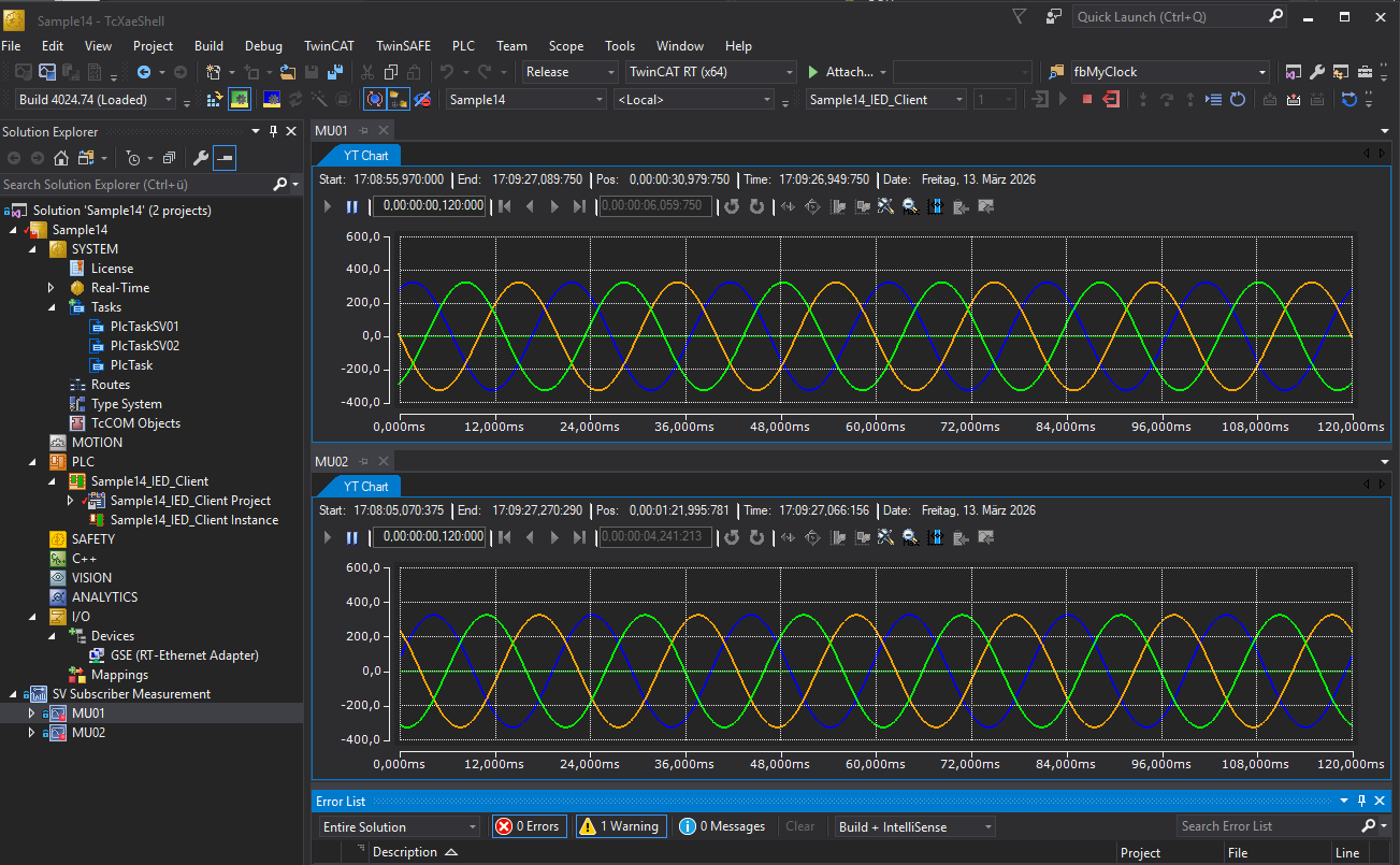
Both sample projects: The SV Publisher and the SV Subscriber also contain a TwinCAT Measurement Scope project. These projects are not automatically created by TwinCAT Telecontrol Configurator. They were manually added to the TwinCAT SV Publisher/Subscriber PLC project. As soon as you have started both projects and the network adapter has been configured correctly beforehand, the data sent and received can be recorded in the measurement scope project. However, you may need to adapt the TwinCAT network addresses (NetIDs) to your actual configuration in the Measurement project beforehand. Right-click on "SV Subscriber Measurement/MU01" in the project tree and select "Change Target System" from the context menu. Repeat the same for "SV Subscriber Measurement/MU02". Proceed similarly in the TwinCAT SV Publisher project.
If the recording in the sample project on the SV Publisher page is active, you should see an image similar to the one below (zoom in until you see sine waves).
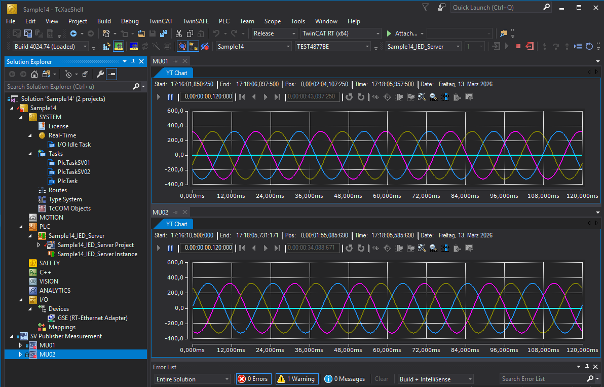
If the recording in the sample project on the SV Subscriber page is active, you should see an image similar to the one below (zoom in until you see sine waves).