Notes
Notes on the sample program of the slave system
- The sample program shows the slave system (system environment B). This requires a controller with an EL1252 EtherCAT Terminal. You can either use an Embedded PC, to which the terminal is connected on the right-hand side, or an IPC with an EtherCAT connection, e.g. an RJ-45 connection to the EK1100 Coupler with the terminal. (See also Configuration)
- If necessary, read in the I/O configuration again and link the variables as follows:
- nIntTime → EL1252, PDO: Latch/ LatchPos1
- aEcMasterAmsNetId → device (EtherCAT), PDO: InfoData/ AmsNetId
- bOut → (optional) EL2202-0100, PDO: Channel 1/ output
- In the sample program, the internal time value (nExtTime) is incremented according to the expected input signal (50 ms period → rEventTimeStep = 5·107) when an incoming positive edge event is detected at the EL1252 input. Select the appropriate value for rEventTimeStep, depending on the expected cycle duration:
nExtTime := nExtTime + LREAL_TO_ULINT(rEventTimeStep);
The addition of a constant time value to a base time value for the time stamp of the external time depends on an incoming (positive) edge. This causes an external time stamp to be mapped by the external clock. An edge is always determined by comparing the current internal time stamp supplied by the EL1252 with the last time stamp in each task run:
IF(current_intTimeSatmp<>last_intTimeSatmp) THEN - Optionally, you can add a YT-Scope-View to visualize the project and
record the following variables from the MAIN program: - nDcOffset (the result of FB_EcExtSyncIsSynchronized from nExtTime and nIntTime)
- bExtTime_Digits and bIntTime_Digits for visualizing the temporal drift or synchronous operation after activation of the synchronization process
- bSynchronized to show that the synchronization has taken place
- The variable bEnableExtSync can be set to TRUE at a desired time.
General information on the master system
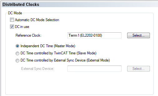
- The master system is not included in this sample. In principle, any timer that can provide a 24 V square wave signal could be used as a master system. The master system shown in the diagram has enabled distributed clocks (DC) for the EL2202-0100 EtherCAT Terminal and set a corresponding task cycle time of 25 ms for an output signal with T = 50 ms. The following code line in the (POU) MAIN is used for generating the output signal:
bOut := NOT bOut; - The EtherCAT master of the master system has distributed clocks (DC) enabled. Further information regarding the setting can be found in the EtherCAT System Documentation in the Setup section under TwinCAT System Manager > Notes on Distributed Clocks.
An EL2202-0100 EtherCAT Terminal in the master system acts as DC timer and also issues the output signal.
- Larger cycle durations, e.g. 1 s, can be converted using a counter variable.