Configuration
Sample configuration for TF6225 TC3 EtherCAT External Sync
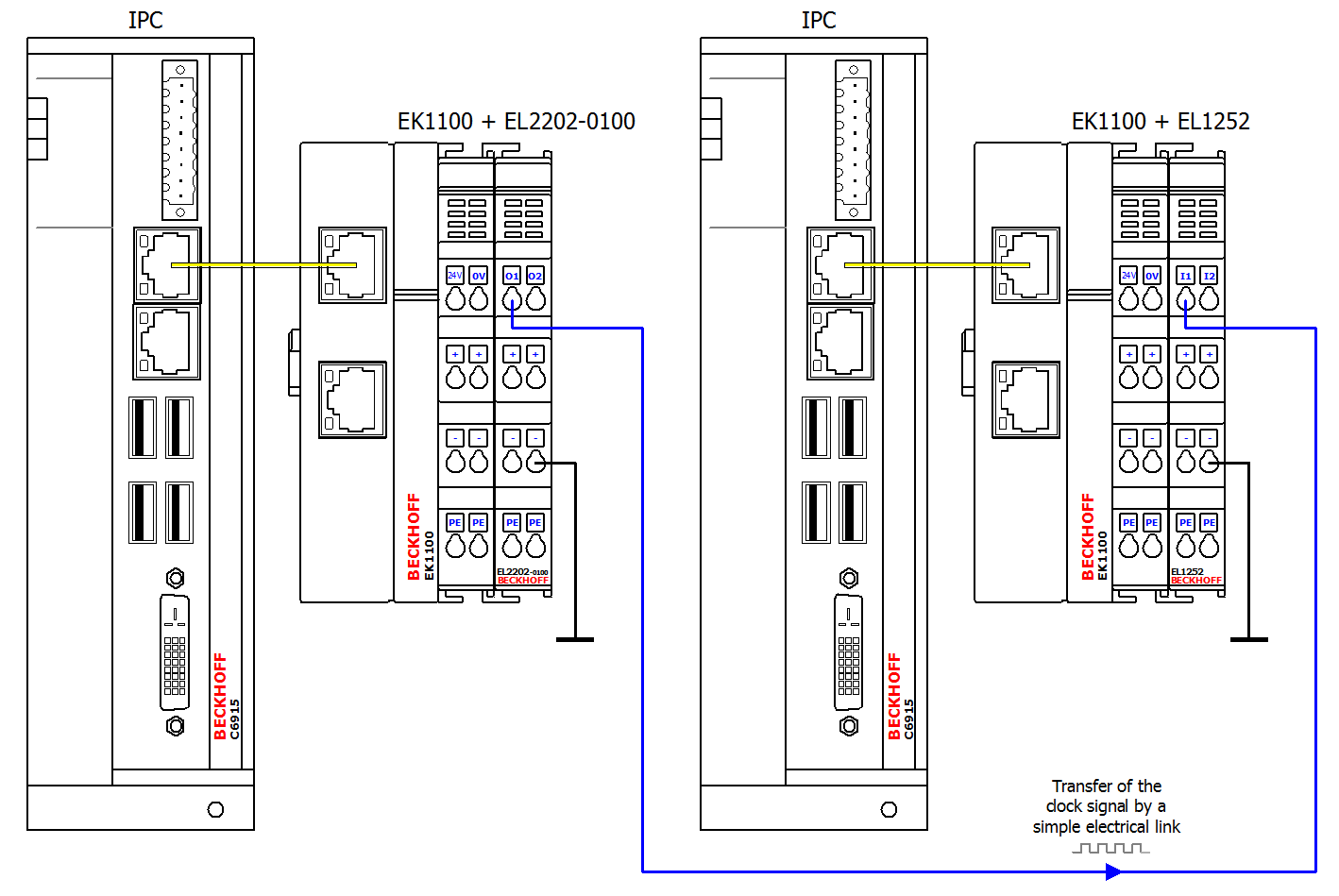
The operating principle of the TF6225 can be illustrated through the configuration of two independent IPC systems. The diagram shows the hardware structure of the master system (clock generator) on the left and the slave system (clock receiver) on the right.
Recording of the internal and external clock with an oscilloscope
After commissioning the system, you can monitor the synchronization via the TwinCAT 3 Scope View, for example.
You can also use an oscilloscope to record the internal and external clocks on a time base. To do this, add an EL2202-0100 EtherCAT Terminal to the slave system. The external clock of the master system can be recorded via the input of the EL1252 EtherCAT Terminal and can serve as a reference (trigger), for example. The internal clock of the slave system can be output via a toggling bit at the additionally connected EL2202-0100 EtherCAT Terminal. If external synchronization is not active, the time drift can be recognized by the fact that the two signals are not fixed in time relative to each other.
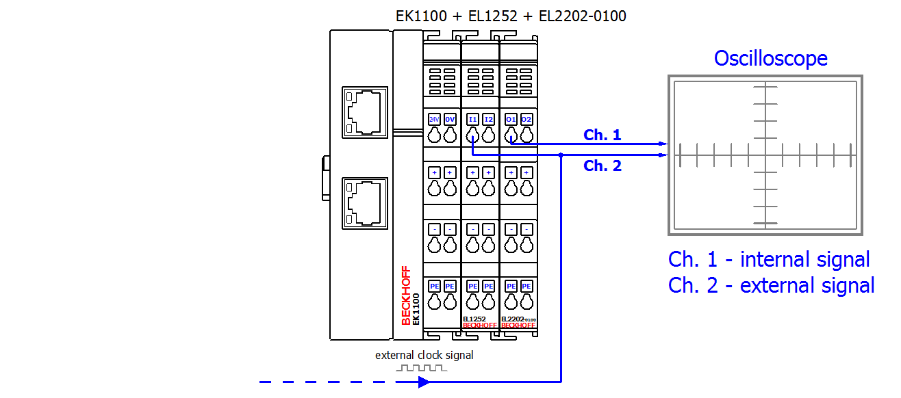
 | The EL2202-0100 EtherCAT Terminal is the extended distributed clocks version of the EL2202. It can be obtained from Beckhoff, or it may be possible to set it up by reprogramming the EL2202. Further information can be found in the documentation EL2202, EL2252 – two-channel digital output terminal. |
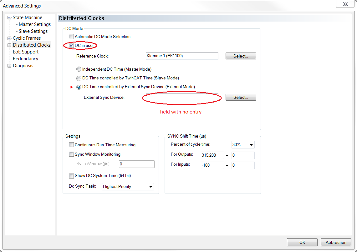
EtherCAT master configuration of the slave system for external DC synchronization via the EL1252 in TwinCAT 3 Engineering
The EtherCAT master of the slave system for external synchronization can be configured in TwinCAT 3 Engineering under advanced device settings. To open the advanced settings, double-click on the EtherCAT device in the TwinCAT project tree. Select the EtherCAT tab and click Advanced Settings… Select the Distributed Clocks entry in the navigation tree in the dialog that opens. Configure the EtherCAT master of the slave system according to the following diagram.