Quick start
The following chapter provides a quick start to the TwinCAT OPC UA I/O Client. In these instructions, the connection to a Sample OPC UA Server is set up, which offers some variables in its namespace. These variables are added to the process image of the TwinCAT OPC UA I/O Client and then linked to PLC variables.
 | Sample OPC UA Server The Sample OPC UA Server is delivered together with the TF6100 OPC UA Client setup and is located in the installation directory of the client. Alternatively, you can also use the TwinCAT OPC UA Server instead of the Sample OPC UA Server to provide a few variables via OPC UA. |
The steps are described below in the order in which they are performed:
- Starting the Sample OPC UA Server
- Creating a TwinCAT project
- Reading the OPC UA variables
- Starting the code generation
Starting the Sample OPC UA Server
- 1. In Windows Explorer, navigate to the installation directory of the TF6100 FunctionSample and then to the subdirectory "SampleServer".
- 2. Start the file TcOpcUaSampleServer.exe as administrator.
- The server is started in a console window and can then be accessed at the following OPC UA URL:
opc.tcp://localhost:48030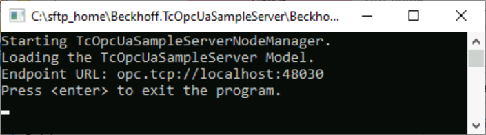
| You can confirm the message regarding the limited runtime. |
Creating a TwinCAT project
- 1. Open the TwinCAT XAE Shell.
- 2. In the File menu, select the command New > Project.
- 3. Add a PLC project to the project.
- A new TwinCAT project including PLC project was created.
Reading the OPC UA variables
- In this step, the TwinCAT OPC UA Client is used to establish a connection to the server and read in the variables available there.
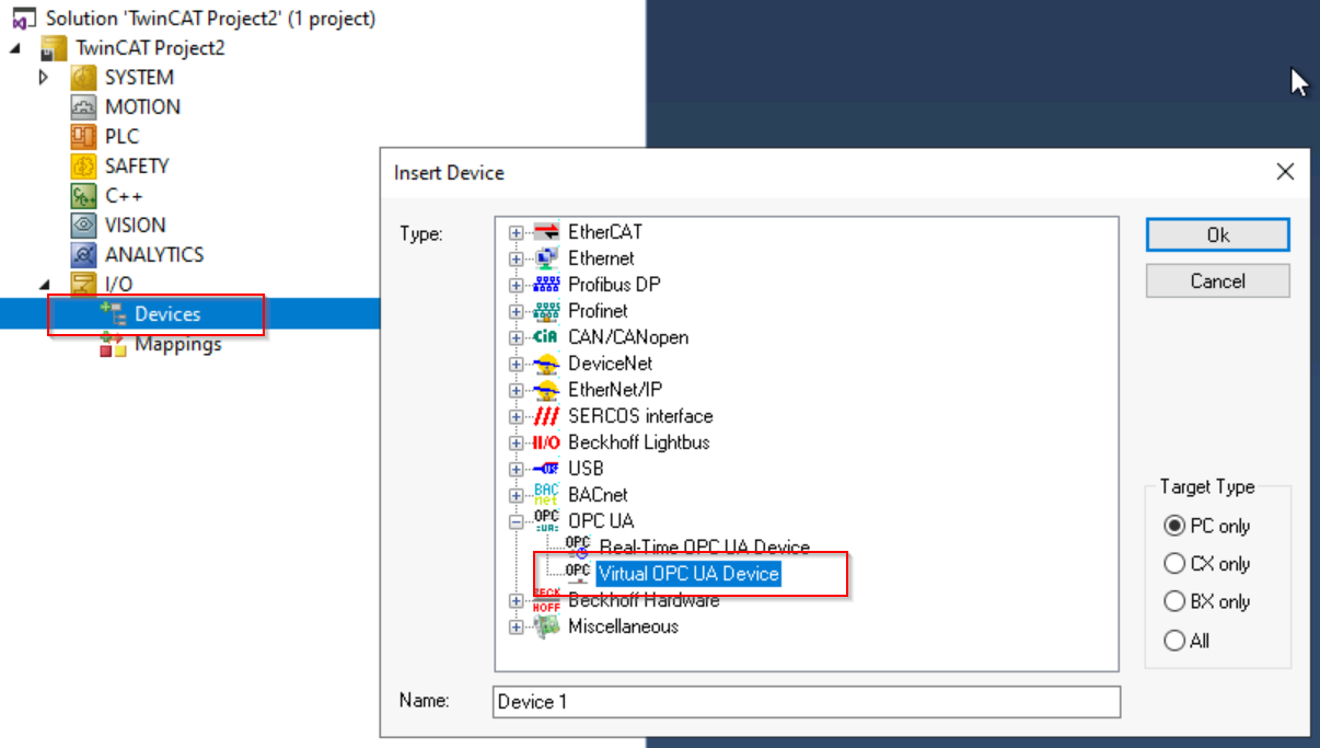
- 1. Add a new I/O device to the TwinCAT project.
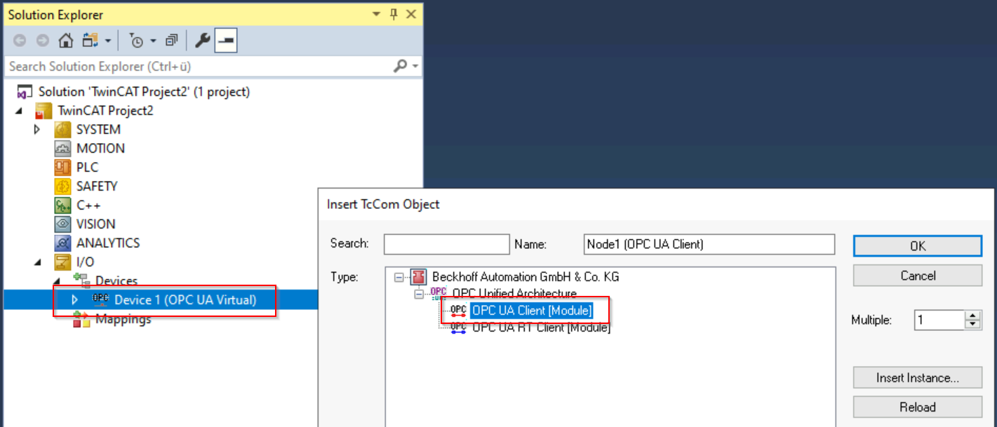
Use "OPC UA Virtual Device" as the device type - 2. Add an OPC UA Client to the device
- 3. Open the settings of the OPC UA Client by double-clicking on the client.
- 4. Navigate to the Settings tab. Enter the server URL of the OPC UA Server. In this sample this is "opc.tcp://localhost:48030".
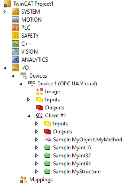
- 5. Click Add Nodes. A connection to the server is established and the address space of the server is displayed in a separate dialog.
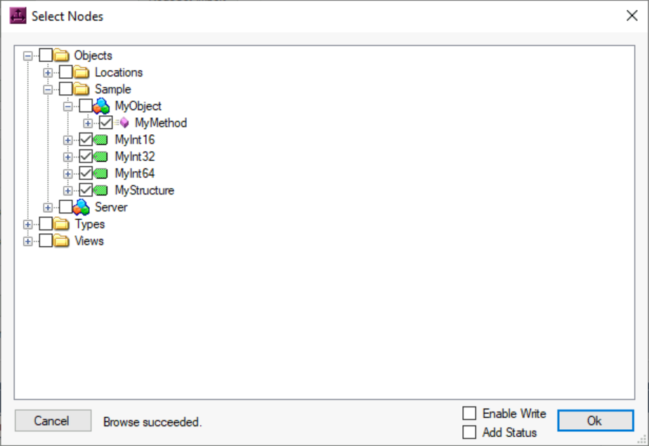
- 6. Select the nodes shown above and click the Ok button.
- The variables and the method for the process image of the client have been added.
Starting the code generation
- Automatic code generation should be used to generate PLC variables to match the added OPC UA nodes. The generated PLC variables are automatically linked to the nodes. Alternatively, you can perform the mapping manually.
- 1. Double-click the OPC UA client.
- 2. In the Settings tab, select the DataType Settings
section.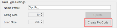
- 3. Click the Create Plc Code button, which starts the code generation.
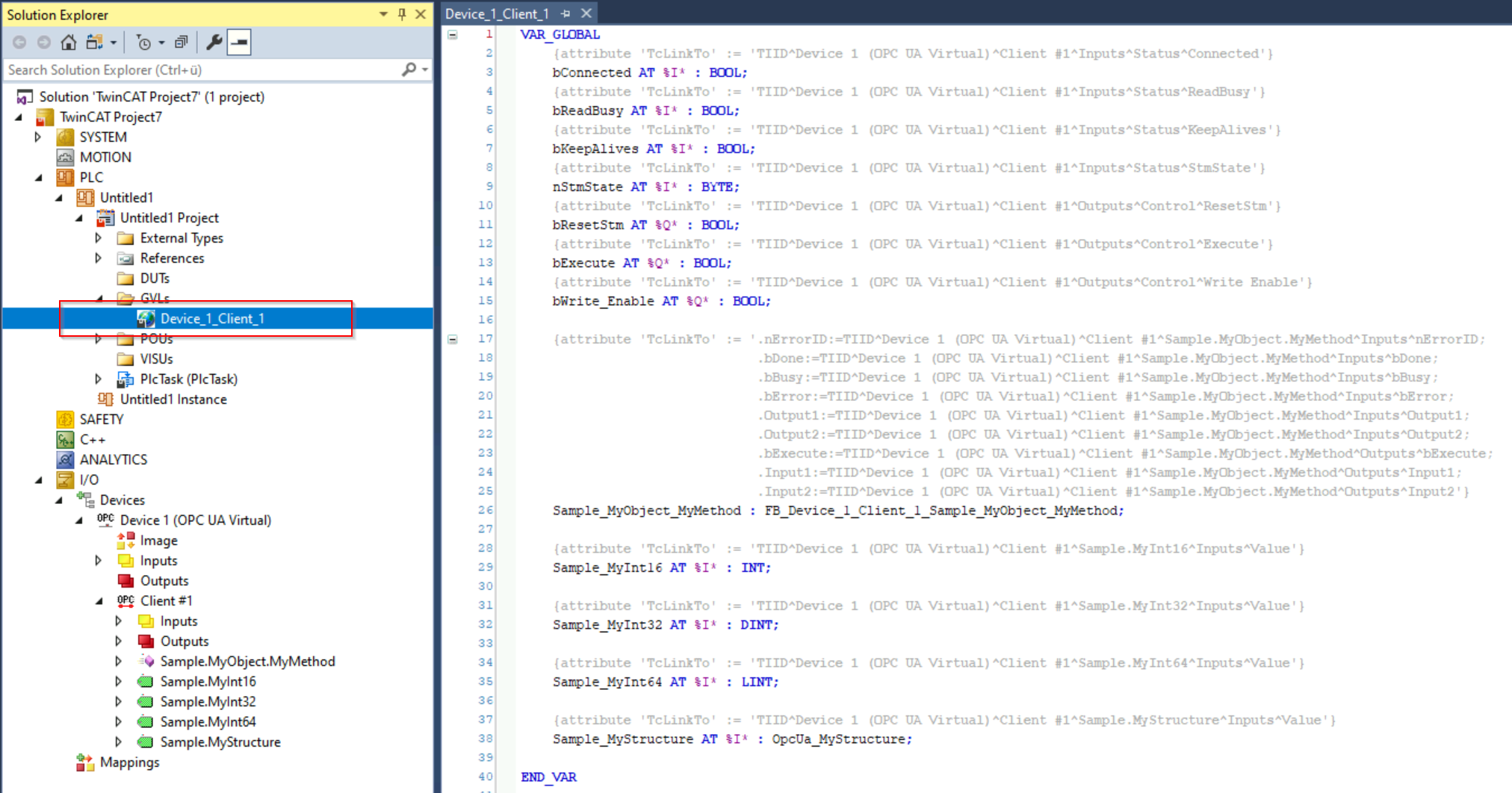
- The code generator creates a GVL in the existing PLC project whose name is derived from the OPC UA Client device name. PLC variables have now been automatically created within the GVL and linked to the corresponding nodes in the process image of the I/O device via the "TcLinkTo" pragma.
- 4. Activate the configuration.
- The values of the OPC UA nodes are read from the server and written to the PLC variables via the mapping.
| Further information on calling the method Further PLC logic is required to call the method. For this purpose, a suitable function block has already been created by the code generation and provided with the corresponding input/output parameters, see chapter Method calls. |