Set control parameters for position control
Start test movement
- The MC3 FluidPower axis was moved during manual operation;
see Move the axis in manual operation using Motion UI.
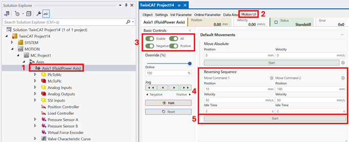
- 1. Double-click the Axis object
- 2. Opening the Motion UI tab
- 3. Apply power to the axis by clicking Enable All
- 4. In the Default Movements card, set the reverse operation parameters to match your motion profile.
- 5. Start of the movement
Set the controller
- 6. Double-click the Position Controller object
- 7. Open the Init Parameter tab
- 8. Optimization of Control Parameters (see also Init Parameter)
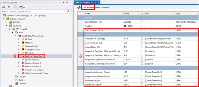
- If necessary, increase any previously set limits on the control signal Minimum/Maximum Output to values permitted for the hydraulic system.
- Set Integral Gain and Derivative Gain to 0.0
- Increase the Proportional Gain until the output signal begins to oscillate
- Slight reduction of the Proportional Gain
- If necessary, adjust the Feed Forward Factor to bring the actual velocity closer to the target velocity
- Set Integral Gain to reduce the residual error at the target position
- Limiting the velocity windows: Integrator Threshold, Minimum/Maximum Velocity of the I-component to prevent over-integration during motion and the resulting overshoot.
- Limiting the Integrator Lag Window Minimum / Maximum of the I-component to prevent residual oscillation at the target position.
The recommended value for the Integrator Lag Window Minimum is 4 times the resolution of the position measurement system.
The Integrator Lag Window Maximum is related to the residual position lag in pure P-control.
The next step is the integration of the FluidPower axis with the PLC;
see Link axis objects to a PLC