Commissioning the FluidPower axis (valve-controlled axis)
The following figure shows an example schematic of a differential cylinder whose position and pressure/force are to be controlled via a 4/3-way proportional valve.
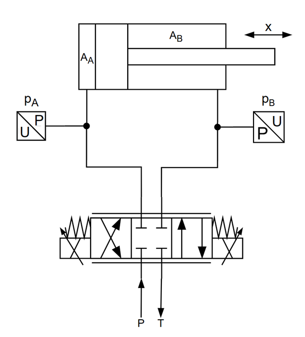
The following section provides a step-by-step description of how to perform commissioning of the position and pressure control of such an axis, using an example with the following components.
- 50/32 mm hydraulic differential cylinder
- Absolute SSI encoder, 0.1 µm resolution
- Analog 4/3-way proportional valve with analog output terminal
- Pressure sensors A/B, 0–400 bar with an analog input terminal
The first step is to create a FluidPower axis;
see Adding an axis