Init Parameter
General
Name | Default value | Unit | Type | ||
|---|---|---|---|---|---|
Position Interpretation | Incremental |
| |||
| Maximum Absolute Counter Value (Visibility depends on position interpretation) | 1048575 | INC | UDINT | |
Position Data Range | FullRange |
| |||
| Minimum Counter Value (Visibility depends on the position data range setting) | 32-bit encoder system
| INC | LINT | |
| Maximum Counter Value (Visibility depends on the position data range setting) | 32-bit encoder system
| INC | LINT | |
Feedback Velocity Source | HardwareProvidedIfAvailable |
| |||
Position Interpretation
The Position Interpretation parameter defines the semantics according to which the values are transmitted by the position encoder and interpreted by the MC3 axis.
Incremental
The Incremental setting does not use the absolute properties of the physical feedback system, but can be used with both incremental and absolute encoder systems. After starting the controller, homing is required to initialize the actual position of the axis (IsPositionValid = FALSE).
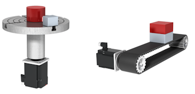
Usage: This setting is suitable, among other things, for axes that move continuously in a coordinate direction. Examples of such mechanisms include rotary indexing tables, conveyor belts, and linear axes with incremental encoders.
AbsoluteFullRange
The AbsoluteFullRange setting is typically used with multi-turn or single-turn absolute encoders. The MC3 axis takes into account the entire data range of the data type in the I/O device mapping (FullRange). The maximum number of increments corresponds to the upper limit of the data type. The size of the data type is specified in the protocol used.
When the controller is powered on or restarted, and position limits are enabled, the axis signals IsPositionValid = TRUE. Configuring and enabling the software-based position limits for the axis allows the axis position to be restored after the controller is restarted. This applies to at most one overflow of the transmitted increments. The position limits must be selected such that the resulting possible travel path of the axis is less than the encoder’s counting range (FullRange).
If the position limits are disabled, the axis indicates this by IsPositionValid = FALSE.
Homing is not required with AbsoluteFullRange.
The “Encoder Mounting Offset” parameter (drive and/or encoder object below the axis) allows you to set an initial offset that is loaded when the controller restarts.
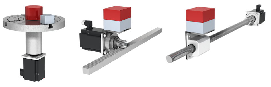
Usage: This setting is suitable for axes that move within a fixed, defined range. Examples of such mechanisms include ball screw or rack and pinion systems with a position range of up to 4096 revolutions (e.g., AX8000 with multi-turn encoder), rotary indexing tables with a positioning range from 0° to 360° without a modulo function (e.g., with a single-turn encoder and a gear ratio of i = 1).
AbsoluteUserDataRange
The same boundary conditions apply as for the setting. AbsoluteFullRange. In addition, the parameter Maximum Absolute Counter Value is displayed and taken into account:
Maximum Absolute Counter Value
Unique maximum number of increments that the encoder system transmits (within the limits of the data type used). For example, the default value is set to 2^20-1.
Usage: The same examples apply to this setting as they do to the AbsoluteFullRange option.
AbsoluteModulo
The position increments are transmitted by the I/O device using modulo logic. For example, if one revolution of the encoder system corresponds to the modulus of the MC3 axis, the position is unique within this range. The axis indicates IsPositionValid = TRUE.
Usage: This setting is suitable for axes that move continuously in a coordinate direction and are equipped with an absolute encoder system. The Modulo function of the drive hardware is enabled. Examples of such mechanisms include rotary indexing tables or conveyor belts in which the gear ratio does not correspond to 2n.
Position Data Range
The Position Data Range parameter defines the value range of the encoder system that is used for position calculation. This refers to the raw value received from the drive or encoder via the process data (PDO mapping) and enables the detection and handling of overflows. The parameter can only be changed at configuration time, not at runtime.
FullRange
Position overflow is based on the data type limits of the respective encoder system. For a signed 32-bit encoder system (e.g., CoE DS402 Drive (AX8000), SoE Drive (AX5000), EtherCAT encoder), this implicitly means a value range from -2147483648 to 2147483647. For an unsigned 32-bit encoder system (e.g., MDP742 Drive (selected ELM72xx), SSI encoder), this implies a value range from 0 to 4294967295.
UserDefined
This parameter value allows you to manually enter the range limits used to determine an overflow. Two additional parameters for entering the upper and lower limits will be displayed:
- Minimum Counter Value
- Maximum Counter Value
Feedback Velocity Source
Specifies the source of the actual velocity (AXIS_REF.McToPlc.Act.Velocity). The velocity can either be obtained from the hardware being used or calculated internally by differentiating the actual position value.
HardwareProvidedIfAvailable (Default value)
Uses the velocity provided by the hardware. If no entry for the actual velocity is mapped in the process data, it is automatically calculated internally.
InternallyCalculated
Velocity is always calculated from the derivative of the actual positions. Actual hardware velocities are ignored, even if they are available.
HardwareProvided
The velocity is always taken directly from the hardware feedback. This requires linking the actual velocity via process data (PDO mapping). If the mapping is missing, this will result in an error when the configuration is started.
Scaling
Name | Default value | Unit | Type |
|---|---|---|---|
Position Scaling Numerator from Hardware | 360 | [PosUnit]/INC | LREAL |
Position Scaling Denominator from Hardware | 1048576.0 |
| LREAL |
Encoder Mounting Offset | 0.0 | [PosUnit] | LREAL |
Direction Inverted |
|
| BOOL |
Velocity Scaling Numerator from Hardware | 1.0 | [PosUnit]/(INC*s) | LREAL |
Velocity Scaling Denominator from Hardware | 1.0 |
| LREAL |
The position scaling factor is divided into a numerator and a denominator. It is used to convert the path increments into axis positions or to calculate a user unit from encoder increments.
Position Scaling Numerator from Hardware
Position Scaling Numerator From Hardware is the feed rate that the application applies when the output shaft has completed one revolution.
Position Scaling Denominator from Hardware
Position Scaling Denominator From Hardware is the number of increments that the drive outputs when the motor shaft has completed one revolution.
Example 1 on position scaling:
Motor without gear unit with 100 mm pinion on AX5000 with default settings:
- Numerator: 100 mm
- Denominator: 1048576
Example 2 on position scaling:
Motor with gear unit with i=10 on turntable on AX5000 with default settings:
- Numerator: 360° / 10 = 36°
- Denominator: 1048576
Encoder Mounting Offset
An offset used to correct the position of an encoder system or align it within the machine coordinate system, thereby defining the machine-specific zero point. This offset is restored when the controller is restarted.
Direction Inverted
The Direction Inverted parameter can reverse the counting direction of the encoder or drive:
FALSE: The polarity of the axis movement agrees with the counting direction of the acquisition hardware.TRUE: The polarity of the axis movement is in the opposite sense to that of the counting direction of the acquisition hardware.
| |
Risk of injury from unexpected movements If the counting direction of the encoder and the motor polarity do not match, the axis will perform unexpected movements.
|

Velocity Scaling Numerator from Hardware
Used to calculate the actual velocity value from the encoder pulses.
Velocity Scaling Denominator from Hardware
Used to calculate the actual velocity value from the encoder pulses.
Dead Time Compensation
A requirement for high-precision conversion of positions into times and vice versa is precise dead time compensation of the axes.
Name | Default value | Unit | Type | |
|---|---|---|---|---|
Dead Time Compensation | NonlinearShift |
| ||
| Additional Time Shift from Hardware | 0.0 | ms | LREAL |
Dead Time Compensation
Specify how the compensated target value and actual value are to be calculated. The dead time is automatically determined during EtherCAT initialization.
Additional Time Shift from Hardware
Additional offset of the automatically calculated dead time to compensate for the current position.
Connection
Name | Default value | Unit | Type | |
|---|---|---|---|---|
AMS address | 0.0.0.0.0.0:0 |
|
| |
| .netId | 0.0.0.0.0.0 |
| AMSNETID |
| .port | 0x0000 |
| WORD |
Channel Number | 0 |
| UDINT | |
EtherCAT Slave Oid | 00000000 |
| OTCID | |
AMS address
Information about the address of the assigned hardware drive (read-only); no manual configuration is required. It is used for communication purposes.
Channel Number
Information about the channel number of the assigned hardware drive (read-only); no manual configuration is required. It is used for communication purposes.
EtherCAT Slave Oid
Object ID of the EtherCAT slave.
Status Mask
Name | Default value | Unit | Type |
|---|---|---|---|
Status Word Error Mask | 0x0008 |
| WORD |
Actual Position Filter
Name | Default value | Unit | Type | |
|---|---|---|---|---|
Filter Type | None |
| ||
| Filter Time Position | 0.0 | s | LREAL |
| Filter Time Velocity | 0.0 | s | LREAL |
| Filter Time Acceleration | 0.01 | s | LREAL |
| Filter Time | 0.001 | s | LREAL |
Filter Type
None
No filter is applied.
PT1-Filter
This is a first-order delay element (digital low-pass filter, proportional element with first-order delay) used to smooth out noisy signals (actual value). The PT1 filter is applied independently to the three actual values: position, velocity, and acceleration. Each variable has its own filter time constant. The filter time constants should be selected from the positive range of values. The value 0.0 disables filtering for the corresponding variable. The larger the filter time constant, the more the actual value is smoothed, and the greater the delay.
Because the variables are filtered separately, the output values are not necessarily consistent with each other.
MovingAverage-Filter
The moving-average filter calculates the arithmetic mean over a sliding time window of the last N input values and is thus a simple FIR low-pass filter (with a finite impulse response).
The moving-average filter is applied independently to the three actual values: position, velocity, and acceleration. Each variable has its own window length: N. The window length is calculated as the quotient of the parameterized filter time and the cycle time. The maximum window length is 1000 data points. The dead time is equal to half the window length.
Since the variables are filtered separately, the output values are not necessarily consistent with one another.
With a filter time of 0.0, the actual value is processed immediately and is not filtered. A long filter time results in significant smoothing and increases the dead time.
KalmanFilter3x1
The 3x1 Kalman filter estimates a set of position (s), velocity (v), and acceleration (a) values based on the continuous actual position values. On the one hand, this serves to reduce noise; on the other hand, the calculation of (s, v, a) is performed consistently, i.e., taking into account the interdependence of these variables. 3x1 indicates that the filter has three output variables (s, v, a) and one input variable (s).
It is often advantageous for (s, v, a) to be consistent with one another. In particular, the Kalman filter is recommended when coupling an axis to an encoder signal.
The 3x1 Kalman filter is configured using the “Filter Time” parameter, which defines the time scale used to calculate (s, v, a). The choice of this parameter represents a trade-off between noise reduction and dynamic response. A longer filter time results in greater noise reduction but a decrease in responsiveness, and vice versa (see the Filter Time parameter below).
Filter Time Position
This parameter is enabled when the Filter Type is set to PT1 or MovingAverage . The value 0.0 disables position filtering. The filter time constant must be selected from the positive range of values. The larger the filter time constant, the more the actual value is smoothed, and the greater the delay.
Filter Time Velocity
This parameter is enabled when the Filter Type is set to PT1 or MovingAverage . The value 0.0 disables velocity filtering. The filter time constant must be selected from the positive range of values. The larger the filter time constant, the more the actual value is smoothed, and the greater the delay.
Filter Time Acceleration
This parameter is enabled when the Filter Type is set to PT1 or MovingAverage . The value 0.0 disables acceleration filtering. The filter time constant must be selected from the positive range of values. The larger the filter time constant, the more the actual value is smoothed, and the greater the delay.
Filter Time
The parameter is active when the Filter Type is set to KalmanFilter3x1 . The Kalman filter is adapted to the application using a simplified parameterization with a single filter time constant. The larger the filter time constant, the greater the degree of smoothing.