Example "Synchronization movement over two Planar tracks"
This example is an extension of the example “Synchronizing a Planar mover on a track with an axis”, in which the synchronization movement of the Planar mover is carried out via two Planar tracks. The above example is modified so that two Planar tracks are created in the MC Configuration so that the Solution Explorer has the following entries: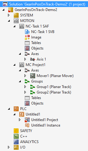
Adapting the PLC project
- 1. Add the libraries Tc3_Mc3PlanarMotion, Tc3_Physics, and Tc2_MC2 to the PLC project, see Inserting libraries.
- 2. Declare the following variables in MAIN:
PROGRAM MAIN
VAR
    mover      : MC_PlanarMover;
    track1     : MC_PlanarTrack;
    track2     : MC_PlanarTrack;
    trail      : MC_PlanarTrackTrail;
    axis       : AXIS_REF;
    power_axis : MC_Power;
    move_axis  : MC_MoveAbsolute;
    state      : UDINT;
    pos1, pos2 : PositionXYC;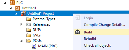
END_VAR- 3. Build the PLC to create symbols of the “PLC mover”, the “PLC track” and the “PLC axis”.
- 4. Link Planar movers, Planar tracks (see example “Coupling a Planar mover to a track and moving it”) and the axis (see example “Synchronizing a Planar mover on a track with an axis”).
 | All previous steps are identical to those in the example “Synchronizing a Planar mover on a track with an axis”, except for the doubling of the number of Planar tracks and the slightly modified code. |
Programming state machines
In the next step, the program code is modified so that the Planar TrackTrail is passed to the GearInPosOnTrack command. The latter is populated beforehand with both Planar tracks, which in this example form a simple network consisting of an L configuration with a blending piece (see Geometric definition):
CASE state OF
  0:
    pos1.SetValuesXYC(100, 100, 0);
    pos2.SetValuesXYC(400, 100, 0);
    track1.AppendLine(0, pos1, pos2);
    track1.Enable(0);
    state := state + 1;
  1:
    IF track1.MCTOPLC_STD.State = MC_PLANAR_STATE.Enabled THEN
      state := state + 1;
    END_IF
  2:
    track2.StartFromTrack(0, track1);
    state := state + 1;
  3:
    pos1.SetValuesXYC(500, 100, 0);
    pos2.SetValuesXYC(860, 100, 0);
    track2.AppendLine(0, pos1, pos2);
    track2.Enable(0);
    state := state + 1;
  4:
    IF track2.MCTOPLC_STD.State = MC_PLANAR_STATE.Enabled THEN
      state := state + 1;
    END_IF
  5:
    mover.Enable(0);
    state := state + 1;
  6:
    IF mover.MCTOPLC.STD.State = MC_PLANAR_STATE.Enabled THEN
      state := state + 1;
    END_IF
  7:
    mover.JoinTrack(0, track1, 0, 0);
    state := state + 1;
  8:
    IF mover.MCTOPLC.STD.CommandMode =
    MC_PLANAR_MOVER_COMMAND_MODE.OnTrack THEN
      state := state + 1;
    END_IF
  9:
    power_axis(Axis := axis,
    Enable := TRUE,
    Enable_Positive := TRUE);
    IF power_axis.Status THEN
      move_axis(Axis := axis, Execute := FALSE);
      state := state + 1;
    END_IF
  10:
    move_axis(Axis := axis,
              Position := 700,
              Velocity := 30,
              Acceleration := 100,
              Deceleration := 100,
              Jerk := 100,
              Execute := TRUE);
    state := state + 1;
  11:
    trail.AddTrack(track1);
    trail.AddTrack(track2);
    mover.GearInPosOnTrack(0, axis.DriveAddress.TcAxisObjectId, trail, 100, 100, track1, 0, 0);
    state := state + 1;
END_CASE

mover.Update();
track1.Update();
track2.Update();
power_axis(Axis := axis);
move_axis(Axis := axis);
axis.ReadStatus();
The two Planar tracks are added to the Planar TrackTrail in State 11. The order is decisive here, as track2 follows track1 and not vice versa. The Planar TrackTrail is passed to the GearInPosOnTrack command as the third argument.
Activating and starting the project
- 1. Activate the configuration via the button in the menu bar
 .
. - 2. Set the TwinCAT system to the "Run" state via the button
 .
. - 3. Log in the PLC via the button in the menu bar
 .
. - 4. Start the PLC via the Play button in the menu bar.
Observe the process in the online view
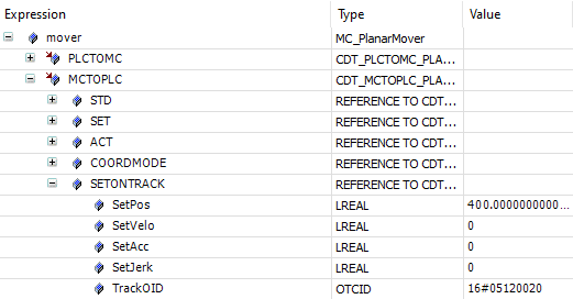
- 5. Observe in the online view how the planar mover initially moves along the first Planar track towards its end:
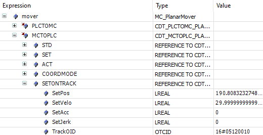
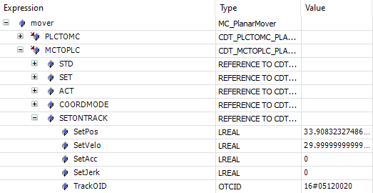
- 6. You will then see how it switches to the subsequent Planar track (see the TrackOIDs):
- 7. Finally, you can see how it comes to a standstill on the second Planar track:
- In this example, the Planar mover also aborts its synchronization movement if the behavior of the master axis requires it to cross the end of the second Planar track (e.g. by selecting the target position of the master axis to be greater than the sum of the lengths of the two Planar tracks). In this case, the Planar mover comes to a standstill at the end of the second track, loses its potential synchronization status and reports an error.
In the event that another Planar track is added to the end of the first, so that a switch is created at its end, the Planar mover clearly “knows” through the Planar TrackTrail which of the two Planar tracks it should turn to and thus continue its synchronization movement (the master axis ultimately produces its setpoints independently of Planar tracks). In this way, a Planar TrackTrail can be used to perform a synchronization movement through arbitrarily complicated track networks on a unique path of any length.
Since the Planar TrackTrail is a pure PLC object that does not communicate via TCOM, but only acts as a container, no cyclic update, such as for the Planar mover, the Planar tracks, or even planar feedbacks (which do not occur in this example), is necessary and a corresponding method is not available.