Group State Diagram
The state diagram describes the state of a Coordinated Motion group. The states described here can be read from the PLC using the function block MC_GroupReadStatus.
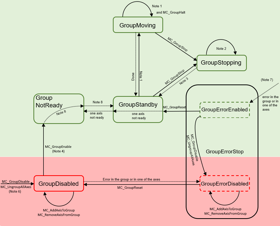
Note | Description |
1 | Applicable for all non-administrative (movement) function blocks. |
2 | In the GroupStopping state, many function blocks can be called, but they are not executed. Exceptions are MC_GroupDisable and MC_UngroupAllAxes, which cancel the stop and create the transition to the GroupDisabled state. |
3 | MC_GroupStop.DONE |
4 | The number of axes in the group (added via MC_AddAxisToGroup) must be equal to the number of axes in the spatial axis convention plus the Additional Axes Count. |
5 | - |
6 | MC_GroupDisable can be called in all states and changes the state to GroupDisabled. When MC_GroupDisable is called in an error state, the state changes to GroupErrorDisabled. |
7 | The state change to GroupErrorEnabled occurs in the axis/group error case from any state in which the group is enabled. |
8 | The state change occurs when "bIsControlLoopClosed" is TRUE for all axes. bPositiveDirection"/"bNegativeDirection" do not have to be enabled. |
9 | - |
10 | MC_GroupReset has no effect if the state is different from GroupErrorStop. MC_GroupReset must be called to exit the GroupErrorStop state. |