Description of the various smoothing methods
CAD/CAM systems use an error-tolerant algorithm to scan the original surface model. The task of the NC is to follow the interpolation point path at high velocity. When CAD/CAM systems are used, the NC program is generated by scanning the original contour created by the user. Then linear and circular blocks are generated depending on the CAD/CAM system. This often results in short blocks ranging from a few mm down to 1/1000 mm.
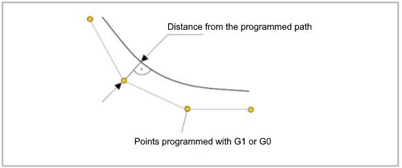
The figure below shows an example of a linear path of a tool track:
Each interpolation point represents an NC block.

Depending on the workpiece type, the contour then describes a relatively smooth path (non-prismatic), or the contour contains corners or edges which must be reproduced or remain recognisable in the workpiece.
A sufficiently high path velocity can only be achieved if the generated NC program has a smooth path of interpolation points. Large fluctuations in block motion paths can lead to highly fluctuating feed rate profiles. This can also have a negative impact on machining results.
Irregular distributions of interpolation points are best interpolated using a highly smoothing method such as the Surface method. However, it is even better to use a suitable filter function in the CAD/CAM system since only this system contains the original contour data.
In all contour smoothing methods, the error tolerance for the main axes forming the feed group is defined in millimetres using the keyword PATH_DEV. If there are more than 3 axes, the tolerance of the angular axes is additionally specified in degrees using the keyword TRACK_DEV.