Programming modulo axes
The default mode for modulo programming supports the specific definition of the direction of rotation and position by programming 2 signs and limiting to maximum one revolution in absolute dimensions.
Syntax: | |
<axis_name> [ + | - ] <pos> | |
<axis_name> | Designation of modulo axis. Long axis designations are not supported (e.g. "C_MODULO"). |
+ | - | The 1st sign after the axis name always determines the direction of rotation: - means rotation clockwise (cc) + means rotation counter-clockwise (ccw) no sign means rotation in the direction of the shortest way (optimised alignment) |
<pos> | Axis position in [°]. The position value can be combined with an additional sign to specify an absolute dimension. The assignment of sign and position value can be forced to execute the shortest way by brackets [..]. |
Notice | |
The programming of 2 signs (direction and position) is only permitted if the axis has the "Modulo" axis mode P-AXIS-00015). Positioning is always executed on the shortest way if no sign is programmed directly after the axis name. In addition, there is also an option to change to a mode that always positions on the shortest path (section Positioning on the shortest way). In this mode, programming 2 signs is also permitted. However, evaluation is based on the following rule: -- => + (minus minus is plus) +- => - (plus minus is minus) -+ => - (minus plus is minus) ++ => + (plus plus is plus) |
Programming in absolute dimensions (G90):
- The value assigned to the axes (target point) is shifted to the modulo range. Therefore, a maximum of one revolution can be moved.
- The value may be a numerical expression such as [3*2+5] , P1 , [P1+P2-3] , [-30].
- The first sign of the value after the axis name always defines the direction of rotation. Every further sign is evaluated as a part of the (absolute) position definition.
Example (assuming: 360° modulo)
- If programmed position = current position, no motion.
- The motion path of a modulo axis is not limited by software limits.
Programming in incremental dimensions (G91)
- The value assigned to the axis indicates the amplitude of rotation of the axis with reference to the previous position. The first sign of the value after the axis name always defines the direction of rotation. Additional signs are not permitted in incremental programming.
Example (assuming: 360° modulo)
- If the value is greater than the modulo value, the number of revolutions is taken into account. Therefore, a motion of more than one revolution is permitted.
The following V.A. variables permit read access to the current axis-specific modulo settings
V.A.MODE[i] | supplies the axis mode according to the axis table, |
V.A.MODULO_VALUE[i] | os used to read the modulo range |
Programming Example
Programming examples of modulo programming in absolute dimensions
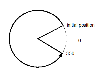
G90 G1 C+350 <=> Go to position 350 in + direction
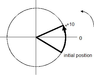
P1 =+10
G90 G1 C+P1 <=> G1 C+10 <=> Go to position 10 in +direction
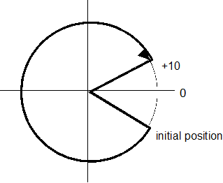
P1= -350
G90 G1 C-P1 <=> G1 C-[-350] <=> G1 C-[10] <=> Go to position 10 in - direction
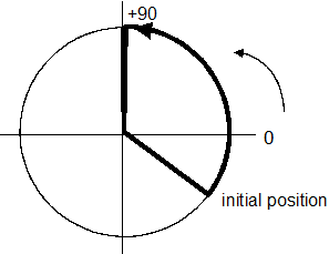
G90 G1 C+450 <=> G1 C+[450 mod 360] <=> Go to position 90 in + direction
Programming Example
Examples of correct programming:
Programming Example
Examples of incorrect programming:
None because the first sign after the axis name determines the direction of rotation and every additional sign belongs to the position expression.
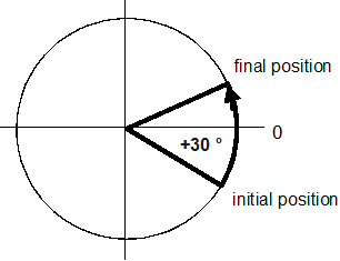
Programming Example
Programming examples of modulo programming in relative dimensions
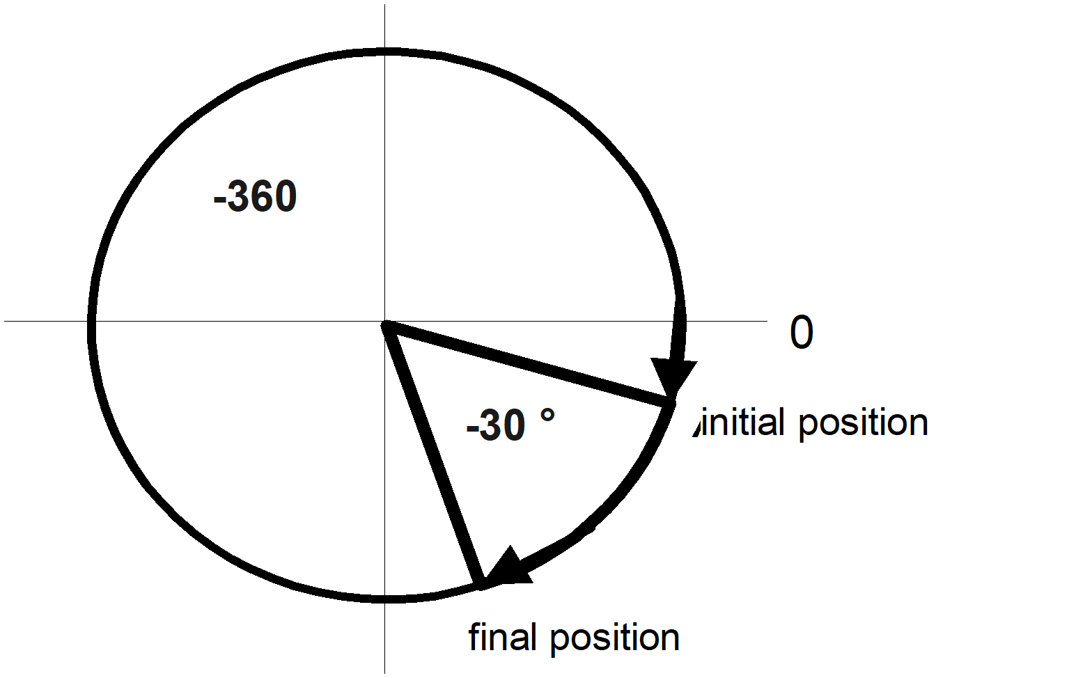
G91 G1 C+30
G91 G1 C-30
Programming Example
Examples of correct programming:
Programming Example
Examples of incorrect programming: