Settings for edge machining (edge_machining.*)
In order to use this functionality, it must be enabled by the parameter P-STUP-00600, or alternatively by P-STUP-00060.
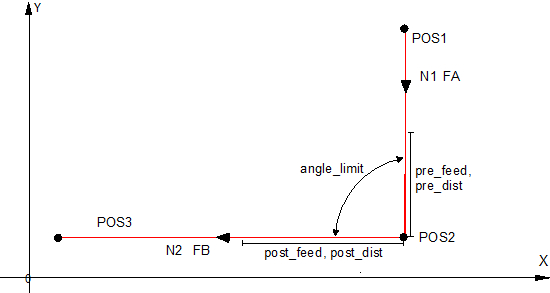
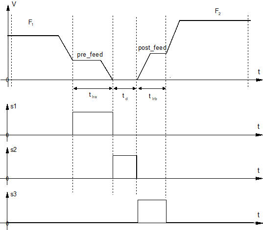
Depending on the machining technology it may be necessary to control the machining process especially on sharp contours (edges). In the case of a sharp edge defined by the angle difference between two contour elements, the path velocity profiler at the edge is modified depending on pre-defined parameters. In addition, three of the command signals are generated. These command signals are derived from the path velocity profile and are supplied to the PLC interface.
- Distance to edge below limit: Signal_1
- Wait time at edge: Signal_2
- Distance after edge below limit: Signal_3
Linear or circular blocks can be programmed as contour elements. No check is made here whether they are inner or outer contours. If the functions Insert chamfers and roundings (G301/G302) or Tool radius compensation (G41/G42) are active, additional contour elements can be generated. They then result in a different knee angle than exists between the two original contour elements.
The following parameters are required to set the edge machining function:
Alternatively, the NC command #EDGE MACHINING is available to parameterise the functionality in the channel parameter list.
If the parameterisation is selected via the channel parameters, the first point in the NC program can be recognised as a corner if it is in the correct position and the parameterised behaviour for edges is then applied there.