Description
Task
The monitor monitors whether the current position lag of a specific axis exceeds its limit. The difference between the output command value and the actual value reported back is referred to as the position lag.
∆s = sref - sact |
Each axis is monitored with different limits at
- standstill and
- during motion
When a position lag occurs, the associated path compound is stopped.
If the actual value position window P-AXIS-00236 (exact stop window, see function description “Position monitoring”, section Description [FCT-A3]) is reached after a motion, the CNC automatically switches back to position lag monitoring “Standstill” for the axis.
Notice | |
Use of the position lag monitor does not release the commissioning engineer or the machine operator in any way from their obligation to exercise due diligence or use additional monitoring systems, e.g. the encoder monitor in the drive controller. |
Prerequisites
In order to use the position lag monitor, the Monitored Axis must be operated in ‘position control’ mode.
Position control may take place in the CNC or in the drive.
Position lag monitoring is not possible for axes that are not operated in ‘position control’ mode, e.g. spindles.
Restrictions
A configured position lag monitor is always active except if:
- tracking mode is active
- measurement at fixed stop is active
- referencing at hardware limit switch is active
The above functions deactivate position lag monitoring temporarily and they re-activate position lag monitoring at the end of each function.
Possible applications
Position lag monitoring is used for:
- drives where the CNC assumes position control
- drives where position control is executed in the drive controller
 | A possible position lag monitor in the drive should always be used with drives which have their own position controller. |
Activation
Position lag monitoring is switched on or off by the P-AXIS-00172 parameter.
| |
Possible risk of personal injury and machine damage Do not deactivate position lag monitoring P-AXIS-00172 otherwise this may result in a collision of axes. |

Warnings, errors and reactions
- Error message P-ERR-70020: The permitted position lag is exceeded when axes are moved. This may be caused, for example, by collision, stiff guides or overload.
- 1. Position controller in CNC: Open the position control circuit and stop the axes using a controlled emergency stop ramp.
- 2. Position controller in drive: Stop the axes using a deceleration that is adjustable in the axis parameter list P-AXIS-00003.
- 3. Stop all axes that are interpolated with the affected axis in the path compound.
- Check the cause of the error message and rectify
- Resetting the controller
- Error message P-ERR-70081: The permitted position lag is exceeded when the axis is at standstill. This may be caused, for example, if an external force is applied to the mechanical system or by a drift in the actual drive position.
- 1. Immediate stop of the affected axis.
- 2. Stop all axes that are interpolated with the affected axis in the path compound.
- Check the cause of the error message and rectify
- Resetting the controller
| The PLC can perform further measures via the controller interface. |
Parameterisation
Position lag monitoring is configured by P-AXIS-00172 for the following types:
- Type 0: no position lag monitoring
- Type 1: Standard method
- Type 2: Linear method
- Type 3: Is no longer supported.
- Type 4: Velocity-independent method
The permitted position lag of a moving axis is calculated for Types 1 and 2 depending on the command velocity. Similarly, in both methods, the permitted position lag can be offset in time by a timer.
The Standard Type 1 uses a parameterisable filter.
The Linear Type 2 is based on the theoretical position lag at constant velocity which can be increased by a factor.
With Type 4, a check is made for a constant velocity-independent limit, even during path motion.
Recommended type selection
Selecting the suitable type depends on the given prerequisites. Recommendation:
- Type 1: K factor is unknown
- Type 2: K factor is known
- Type 4: The axis is operated with speed feedforward control depending on whether control is performed by the CNC or in the drive.
Adjusting and controlling position lag monitoring
Position lag monitoring during axis start-up is adjusted and controlled as follows:
- Select type for position lag monitoring and enter it in P-AXIS-00172.
- Suppress error output of position lag monitor by setting P-AXIS-00176to the value 1. The limits defined by the monitoring type settings are then calculated.
- Test run and observe the actual position lag value and calculated limits in the object browser.
- Set limits P-AXIS-00168 and P-AXIS-00169 taking margins into consideration.
- Release error output of position lag monitor by setting P-AXIS-00176 to the value 0.
| |
Possible risk of personal injury and machine damage Personal injury and machine damage may occur when the error output of the position lag monitor is suppressed by setting P-AXIS-00176 to the value 1. |
Test run
The recommended test run consists of a G1 axis motion without machining action but with the usual load of a typical workpiece on the machine.
Position lag can be observed with the ISG browser.
The “absolute_position_lag” value shows the amount of position lag in the test. The maximum permitted value configured P-AXIS-00168 can be displayed for comparison at “max.position_lag”. “Max.position_lag is determined depending on the method used.
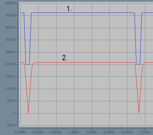
1. | absolute_position_lag: Absolute value of position lag |
2. | max.position_lag: Maximum value of position lag |
Causal system, system run time
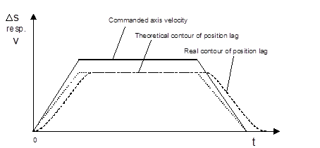
The theoretical position lag ∆s depends on the command velocity v and the effective position controller gain kv as follows:
|
|
|
However, the real axis has a real position lag which is delayed with respect to the theoretical position lag. This delay is caused by:
- a system-specific cycle offset in the position controller in the controller and
- by the system mechanical time constant.
The methods for calculating the permitted position lag do not take this influence into consideration. Therefore, the permitted position lag must be offset by an additional timer (PT1).
- 1. Configure timer with P-AXIS-00170.
Run time with drives with integrated position control
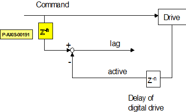
On drives with an integrated position controller, the CNC can additionally perform position lag monitoring.
Due to the run time of the drive bus and calculations in the drive itself (filtering, fine interpolation), the command position value calculated by the controller only becomes active after a delay of possibly several CNC cycles.
To calculate position lag, however, the last transmitted command value and the current actual value are used as standard with the result that the calculated position lag is greater than the actual position lag.
This delay can be compensated by using an older command value to calculate position lag instead of the command value of the current cycle. The parameter P-AXIS-00191 can set which of the past command values should be used to calculate position lag.
Setting the parameter
To set the parameter P-AXIS-00191 proceed as follows:
- Read out position controller gain (kv) from the drive controller.
- Move axis at constant velocity and calculate related position lag with:

- Set P-AXIS-00191 so that the difference between the position lag calculated in the controller and the calculated position lag is minimal.
In general, it is not possible to obtain an exact match between the calculated position lag and the position lag calculated in the controller. The reason for this is that the cycle time of the drive position controller is smaller than the bus cycle time with the result that the correct delay may contain fractions of the bus cycle time.
Alternatively, the position lag calculated in the drive controller can be transmitted to the cyclical process data in the controller. There it can be used for monitoring instead of the position lag calculated in the controller. See the section below for more details.
Using position lag calculated in the drive
Proceed as follows when using the position lag calculated in the drive:
- Configuring position lag in the cyclical process data of the drive
- Activate evaluation of drive position lag by setting the axis parameter P-AXIS-00466.