Six Axis Articulated (S_CBBCBC)
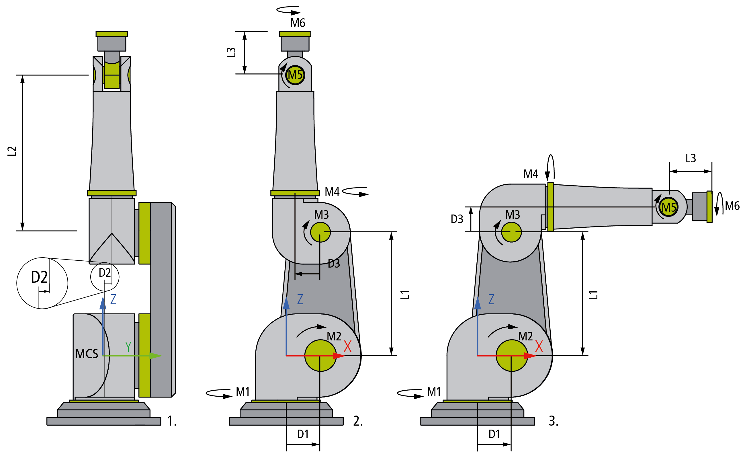
The motor axes of the Serial Six Axis Articulated (S_CBBCBC) Kinematics each are referred to in units of degree. The drawings 1. and 2. above show the kinematics with all axes in zero position. The zero positions of the axes M4 and M6 are defined in a way that the machine coordinate system and the flange coordinate system exhibit the same orientation. The drawing 3. shows the axis M3 in 90° position.
The MCS origin is located within the intersection of the first kinematic joint M1 with the second kinematic joint M2. It is oriented in a way that joint M2 prescribes a rotation around the Y-axis. The center of M1 delivers the X zero coordinate. The intersection of M1 and M2 delivers the Y zero coordinate. The center of M2 delivers the Z zero coordinate.
 | Singular Positions The positions displayed in figures 1., 2. and 3. cannot be approached in cartesian Mode because the robot resides in a singular position. Approaching these positions is only possible in axis mode (Direct Mode). |
Configuration Parameters
Parameter | Description | Type | Unit |
|---|---|---|---|
MCS offset | Static offset to the MCS coordinate frame. |
|
|
X-shift | Static X-offset in MCS coordinate frame. |
| mm |
Y-shift | Static Y-offset in MCS coordinate frame. |
| mm |
Z-shift | Static Z-offset in MCS coordinate frame. |
| mm |
Spatial reference definition | Specification of the spatial reference node. |
|
|
.Translation X | Translation in X-direction. |
| mm |
.Translation Y | Translation in Y-direction. |
| mm |
.Translation Z | Translation in Z-direction. |
| mm |
.Rotation 1 | Rotation angle 1, its interpretation is set by the rotation convention. |
| ° |
.Rotation 2 | Rotation angle 2, its interpretation is set by the rotation convention. |
| ° |
.Rotation 3 | Rotation angle 3, its interpretation is set by the rotation convention. |
| ° |
.Rotation convention | Set the interpretation of the rotation angles. |
|
|
.Spatial reference | Set the spatial frame of reference, 0x0 refers to WCS. |
|
|
.Definition direction | Set the definition direction. |
|
|
Parameters for the Kinematics
For the Six Axis Articulated Kinematics, a serial six axis kinematic, there are the following joint parameters.
Parameter | Description | Type | Unit |
|---|---|---|---|
Arm length L1 | Distance between the motor axes M2 and M3. |
| mm |
Arm length L2 | Distance between the motor axes M3 and M5. |
| mm |
Arm length L3 | Distance between the motor axis M5 and the flange. |
| mm |
Arm offset D1 | Distance between the motor axes M1 and M2 in X-direction. |
| mm |
Arm offset D2 | Distance in Y-direction between the motor axes M1 and M4. |
| mm |
Arm offset D3 | Distance in X-direction between the motor axes M3 and M5. The sign within the example sketch is positive. |
| mm |
General Parameters for the Kinematics
General parameters that apply to any kinematics are described in the following sections:
For all kinematics with tool also applies:
| TF5113 | TwinCAT Kinematic Transformation L4 TF5113 | TwinCAT 3 Kinematic Transformation L4 is subject to legal restrictions and is not included in the TF5400.AdvancedMotionPack workload or included in the TF5400 TwinCAT Advanced Motion Pack Setup from the website. If required, please get in touch with your sales contact. |