Configuration
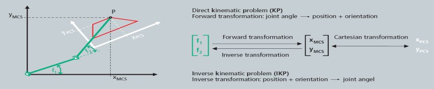
Based on PLCopen, we distinguish between two main coordinate systems (see description Introduction):
- Axis coordinate system (ACS)
- Machine coordinate system (MCS)
Configuring the kinematic transformation channel
- 1. Add all axes (ACS and MCS ) to the NC configuration in the XAE, just like PTP axes. The axes of the ACS are hardware axes and are linked with drives. The axes of the MCS are pure software axes of the simulation encoder type. All ACS and MCS axes that are used in a kinematic transformation channel must be created in the XAE. A delta robot, for example, has three ACS axes (M1...M3) and three MCS axes (X, Y, Z).
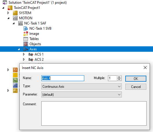
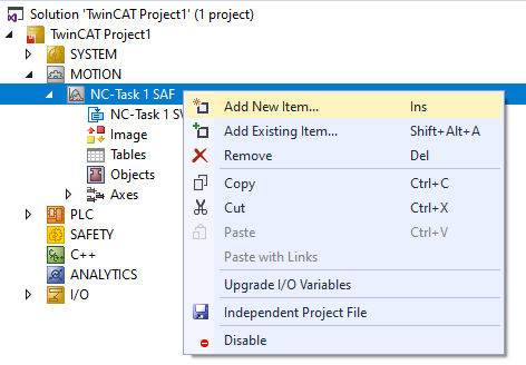
- 2. Right-click on “Axes” and select “Add new item”.
- 3. Then create the axes in the “Insert NC Axis” window, according to the kinematics.
- 4. Add a kinematic channel to the XAE configuration.
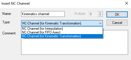
- The addition of a channel creates an instance of a kinematic group.
- 5. Select the channel type: NC channel (for kinematic transformation) for performing a kinematic transformation.
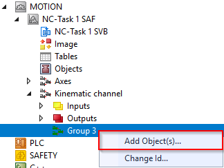
- 6. Add the objects under the group representing the kinematic configuration of the user.
- 7. To start the transformation for a delta robot, select
- Delta Type 1
In addition, optional tools and coordinate systems (UCS) can be created.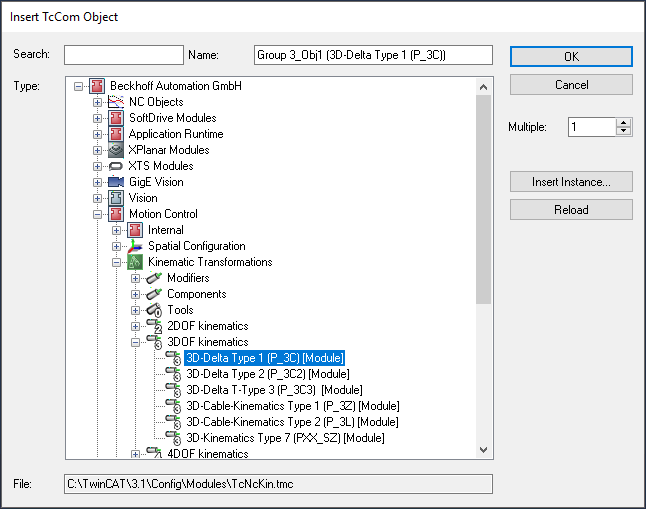
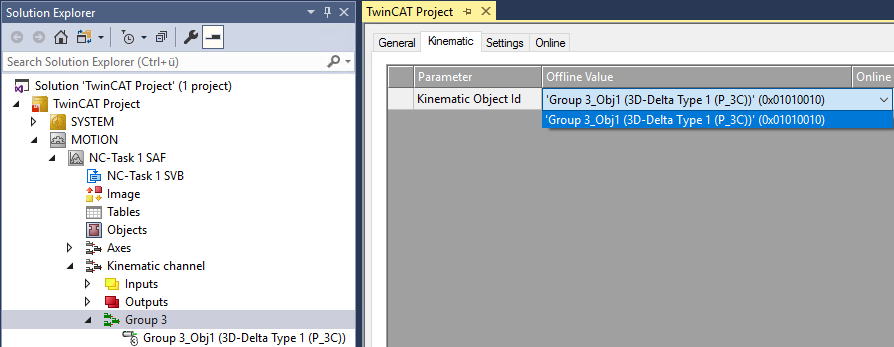
- 8. The transformation group must know which root module is to be called. This is why the object ID of the kinematics (in this case Delta Type 1) must be selected. The kinematic object defines the number of ACS and MCS axes to be used in the PLC (see ST_KinAxes).
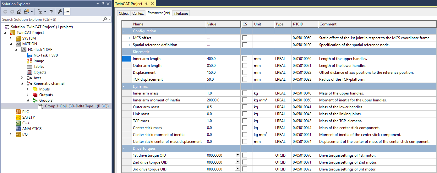
- 9. Parameterize the object parameters according to the kinematics used.
- 10. The transformation can now be activated via the PLC (see Plc Library). To actuate the transformation, define a cyclic channel interface in the PLC and link it with the I/O of the kinematic channel.
in_stKinToPlc      AT %I*     : NCTOPLC_NCICHANNEL_REF;
out_stPlcToKin     AT %Q*     : PLCTONC_NCICHANNEL_REF;