3D-Delta Y Type 4 (P_3C4)
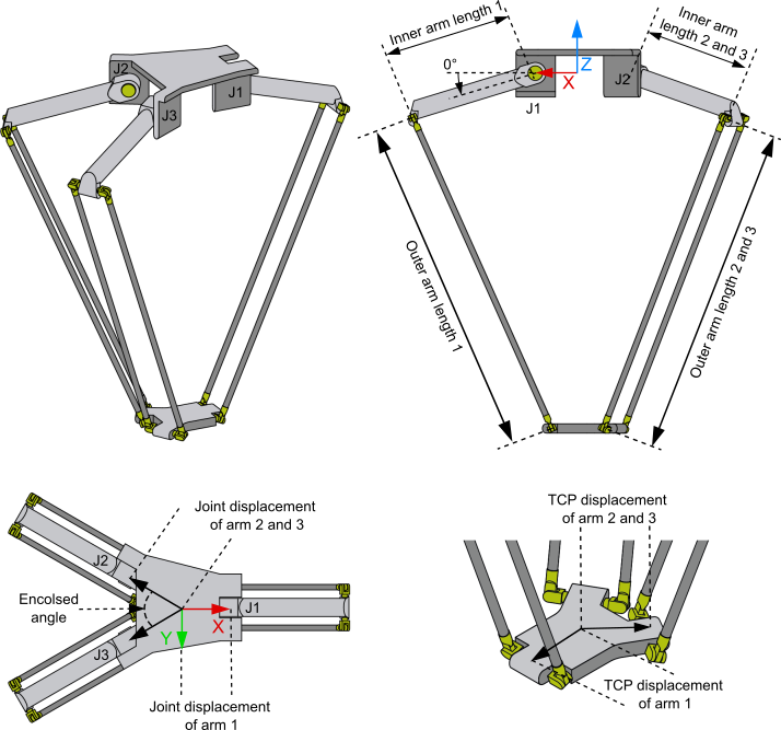
The 3D-Delta Y Type 4 (P_3C4) is structured as shown in the diagram above.
All three arms are suspended at the same level. Unlike 3D-Delta Type 1 (P_3C), the angle between arms 2 and 3 can be specified.
The machine coordinate system (MCS) is located in the middle between the arms at the height of the motors.
All motor axes are scaled in degrees and 0° is defined, as shown in the diagram, with the arrow indicating the positive direction of rotation. This applies to all three motors.
Kinematics parameters
Parameter | Description | Type | Unit |
|---|---|---|---|
Inner arm length 1 | Arm 1: Length from pivot point to pivot point of the inner arm (directly connected to the motor) |
| mm |
Outer arm length 1 | Arm 1: Length from pivot point to pivot point of the outer arm |
| mm |
Joint displacement of arm 1 | Arm 1: The distance from the MCS origin to the motor axis |
| mm |
TCP displacement of arm 1 | Arm 1: Length between the center of the gripper plate and the virtual rotation axes of the outer arm |
| mm |
Enclosed angle | Angle between arms 2 and 3 |
|
|
Inner arm length 2 and 3 | Arm 2, arm 3: Length from pivot point to pivot point of the inner arm (directly connected to the motor) |
| mm |
Outer arm length 2 and 3 | Arm 2, arm 3: Length from pivot point to pivot point of the outer arm |
| mm |
Joint displacement of arm 2 and 3 | Arm 2, arm 3: The distance from the MCS origin to the motor axis |
| mm |
TCP displacement of arm 2 and 3 | Arm 2, arm 3: Length from the center of the gripper plate to the virtual axes of rotation of the outer arm |
| mm |
General Parameters for the Kinematics
General parameters that apply to any kinematics are described in the following sections:
For all kinematics with tool also applies:
Prerequisites
Installation package | Target platform | TwinCAT function |
|---|---|---|
TF5400 TwinCAT 3 Advanced Motion Pack V3.3.57 | PC or CX (x86 or x64) | TF5112 TwinCAT 3 Kinematic Transformation (Level 3) |