3D-Cable Kinematics Type 1 (P_3Z)
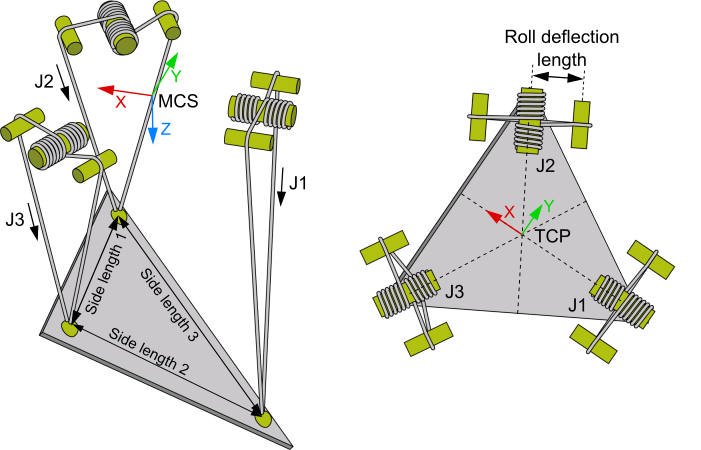
The 3D-Cable Kinematics Type 1 (P_3Z) is structured as shown in the diagram above.
- The zero point of the machine coordinate system (MCS) is centered between the three cable suspension points, with the Z-axis pointing downwards.
- All motor axes are scaled in mm, the arrow indicating the positive direction.
Kinematics parameters
Parameter | Description | Type | Unit |
|---|---|---|---|
Side length L1 | Distance between suspension points 2 and 3 |
| mm |
Side length L2 | Distance between suspension points 1 and 3 |
| mm |
Side length L3 | Distance between suspension points 1 and 2 |
| mm |
Roll deflection length | Distance between the motor shafts and deflection rollers |
| mm |
General Parameters for the Kinematics
General parameters that apply to any kinematics are described in the following sections:
For all kinematics with tool also applies: