4D-Cable-Kinematics (P_4L)
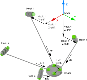
The 4D-Cable Kinematics (P_4L) is structured as shown in the above schematic.
The zero point of the machine coordinate system (MCS) can be anywhere in space. The hooks of the cable/rope are defined starting from the MCS origin.
All motor axes are scaled in millimeters, the arrow indicating the positive direction.
Parameters for joint hooks
Parameter | Description | Type | Unit |
|---|---|---|---|
Hook 1 | Hook of the first cable |
|
|
X-shift | X-position of Hook 1 in relation to the MCS |
| mm |
Y-shift | Y-position of Hook 1 in relation to the MCS |
| mm |
Z-shift | Z-position of Hook 1 in relation to the MCS |
| mm |
Hook 2 | Hook of the second cable |
|
|
X-shift | X-position of Hook 2 in relation to the MCS |
| mm |
Y-shift | Y-position of Hook 2 in relation to the MCS |
| mm |
Z-shift | Z-position of Hook 2 in relation to the MCS |
| mm |
Hook 3 | Hook of the third cable |
|
|
X-shift | X-position of Hook 3 in relation to the MCS |
| mm |
Y-shift | Y-position of Hook 3 in relation to the MCS |
| mm |
Z-shift | Z-position of Hook 3 in relation to the MCS |
| mm |
Hook 4 | Hook of the fourth cable |
|
|
X-shift | X-position of Hook 4 in relation to the MCS |
| mm |
Y-shift | Y-position of Hook 4 in relation to the MCS |
| mm |
Z-shift | Z-position of Hook 4 in relation to the MCS |
| mm |
TCP | Tool Center Point |
|
|
TCP length | Distance between the hooks at the TCP along the X-axis |
| mm |
TCP width | Distance between the hooks at the TCP along the Y-axis |
| mm |
General Parameters for the Kinematics
General parameters that apply to any kinematics are described in the following sections:
For all kinematics with tool also applies:
Requirements
Development Environment Installation Package | Target System | TwinCAT Function |
|---|---|---|
TwinCAT V3.1.4024.7 TF5400 TwinCAT 3 Advanced Motion Pack V3.1.10.30 | PC or CX (x86 or x64) | TF5112 TwinCAT 3 Kinematic Transformation (Level 3) |