"DXD" tab
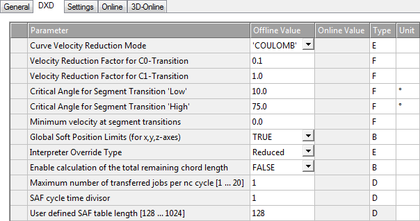
The NCI group parameters are written on the "DXD" properties page.
Curve velocity reduction method
The curve velocity reduction method is only effective for C0 transition (see Classification of Segment Transitions)
Defines of the curve velocity reduction method
0 Coulomb
1 Cosinus
2 VeloJump
3 DeviationAngle (not yet released) |
Method |
Description |
|---|---|
|
Coulomb |
The coulomb reduction method is a dynamic process analogous to the Coulomb scattering. |
|
Cosine |
The cosine reduction method is a purely geometrical process.
Reduction scheme:
For full reduction (down to φ = 0), set C0 = 0.0 and φlow = 0 and φhigh very small but not equal to 0 (e.g. 1.0E-10) |
|
VeloJump |
It is a geometrical procedure for determining the segment transition velocity at a C0 transition. The procedure reduces the path velocity as required, so that the step change in velocity does not exceed the specified limit value. It is calculated based on the following formula: VeloJump factor * cycle time * min (acceleration; deceleration) Further information: |
Velocity reduction factor C0 transition
Reduction factor for C0 transitions. The effect depends upon the reduction method.
C0 ∈ [0.0, 1]
Velocity reduction factor C1 transition
First, V_link is set to the lower of the two segment target velocities:
V_link = min(V_in,V_out).
The geometrically induced absolute step change in acceleration AccJump in the segment transition is calculated depending on the geometry types G_in and G_out, and the plane selection G_in and G_out of the segments to be connected, at velocity V_link.
If this is greater than C1 times the path acceleration/(absolute) deceleration AccPathReduced permissible for the geometries and planes, the velocity V_link is reduced until the resulting step change in acceleration is equal to AccPathReduced.
If this value is less than V_min, then V_min takes priority.
Reduction factor for C1 transitions: C1 ≥ 0.0
Critical angle, segment transition 'high'
Parameters for φhigh (see curve velocity reduction method).
Minimum velocity at segment transitions
Each NCI group has a minimum path velocity V_min ≥ 0.0. The actual velocity should always exceed this value. User-specified exceptions are: programmed stop at segment transition, path end and override requests which lead to a velocity below the minimum value. A systemic exception is a motion reversal.
With the reduction method DEVIATIONANGLE the deflection angle is φ ≥ φ_h, in which case the minimum velocity is ignored. V_min must be less than the set value for the path velocity (F word) of each segment.
The minimum velocity can be set to a new value V_min ≥ 0.0 in the NC program at any time. The unit is mm/sec.
Global soft position limits (for x,y,z-axes)
Parameters for enabling the software end positions of the path (see: Parameterization).
Interpreter override type
Parameter for selecting the path override type (see Path override (interpreter override types)).
Enable calculation of the total remaining chord length
Activates the calculation of the remaining path length. When the calculation of the remaining path length has been activated, it can be extracted via ADS afterwards. See also within the Appendix: Displaying the Remaining Path Length.
Maximum number of transferred jobs per nc cycle [1 … 20]
Maximum number of commands to be transferred per NC cycle. With this parameter it is possible that the SVB task still runs slower than the SAF task and nevertheless sufficiently enough jobs are transposed so that the SAF table does not run out of jobs.
SAF cycle time divisor
The cycle time reduction ensures that the set value in the SAF is not calculated with the SAF cycle time, but with a time that is divided by the value specified here. For highly dynamic motions it may make sense to set the parameter to a value greater than 1, in order to minimize discretization inaccuracies. Increasing the SAF cycle time divisor results in the set value generator being called more frequently internally.
User-defined SAF table length
Parameter that defines the size of the SAF table and therefore the maximum number of cached SAF entries (look-ahead). If an NC program involves sequential movement of many very short segments, increasing this value can help to avoid an unintentional velocity reduction at the segment transitions.