Other Settings
Position Correction


The Position Correction can be activated under MOTION | NC-Task 1 SAF | Axes | Axis 1 | Parameter.
Alternatively, the Position Correction can be activated under MOTION | NC-Task 1 SAF | Axes | Axis 1 | Enc | Parameter.
Similar for other identifiers.
FALSE: The Position Correction is disabled.
TRUE: The Position Correction is enabled.
The variable axis.PlcToNc.PositionCorrection is of data type LREAL and belongs to the structure PLCTONC_AXIS_REF. If Position Correction is enabled, this variable adds an additional offset to the target position. It should be noted that this correction does not affect the software end positions.
Filter Time Position Correction (P-T1)
The filter time for the PT-1 filter, which filters fluctuations within the Actual Position Correction with the filter time set here. See section PT1 Filter for further information on the PT1 filter.
See also:
MC_PositionCorrectionLimiter
The function block MC_PositionCorrectionLimiter adds the correction value PositionCorrectionValue to the actual position value of the axis. Depending on the CorrectionMode the position correction value is either written directly or filtered.
 | To use the |
Backlash
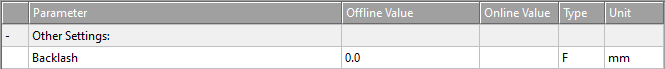
This parameter is only present for compatibility reasons. For more information, visit NC Backlash Compensation.
Error Propagation Mode

For the slave axis the error transmission can be delayed.
‘INSTANTANEOUS’: The error transmission is not delayed.
‘DELAYED’: The error transmission is delayed by the Error Propagation Delay.
The basic idea behind this setting is, that no automatic immediate NC error response is initiated in the event of an error. The user has the option of initiating an individual error response that is precisely tailored to the application.
If a runtime error occurs in a coupled axis, only this axis is switched to an error state without delay by means of an error response, without immediately affecting the other axes in the master/slave group (local error response). Error propagation to the other axes involved is prevented for the parameterized delay time.
During this time, the user is responsible for initiating the required error response (e.g. stopping the master axis or decoupling parts of the master/slave structure). After the parameterized delay time has elapsed, the known NC error reaction comes into effect (global error reaction). This error reaction only affects the axis group to which the faulty axis belongs at this point in time (e.g. the original master/slave group may have previously been divided into an error-free and a faulty group by decoupling).
Notice | |
If the user withdraws the controller enable (MC_Power) from the axis signaling the error, all other axes in the master/slave group are immediately set to a runtime error (subsequent error 0x42A0). |
Error Propagation Delay
The delay time by which error propagation for the slave axis is delayed when Error Propagation Mode ‘DELAYED’ is selected.
If an error occurs at a slave axis during runtime, the corresponding master axis is not set to error state until the time assigned here has elapsed. A state of interest of the slave axis, especially its error state, can be observed by PLC code. In this way, the faulty slave axis can be safely decoupled to safely prevent the entire axis combination from entering the error state.
Couple slave to actual values if not enabled

FALSE: Not coupled.
TRUE: Coupled. The slave axis follows the master actual position while and also when the master is disabled.
Velocity Window und Filter Time for Velocity Window
The coupled slave axis follows the master axis within the Velocity Window. If velocity deviations exceed Filter Time for Velocity Window beyond Velocity Window, an error is output.
Allow motion commands

Allow motion commands to slave axis
In general terms, an axis is in PTP mode all the time. This is about indirectly converting a slave axis into a master axis. Thus it is implicitly decoupled without the need to call on MC_GearOut from the PLC code.
TRUE: A PTP command can be triggered to the slave axis without first setting the axis to PTP mode.
FALSE: Before a PTP command can be triggered to the slave axis, the slave axis must be set to PTP mode.
Allow motion commands to external setpoint axis
FALSE: Before a PTP command can be triggered to the external setpoint axis, the external setpoint axis must be set to PTP mode.
TRUE: A PTP command can be triggered to the external setpoint axis without first setting the axis to PTP mode.
Dead Time Compensation (Delay Velo and Position)

This parameter is only present for compatibility reasons. Do not use it on new projects.
Data Persistence

Data Persistence is used for special encoder problems.
FALSE: Data Persistence is not enabled.
TRUE: Data Persistence is enabled.