Vibration assessment according to ISO 10816-3
Vibration assessment based on ISO 10816-3 is explained in more detail in section Application concepts, see Vibration assessment. The classification based on the calculated RMS values is done directly in the MAIN program. Alternatively, the function blocks FB_CMA_WatchUpperThresholds or FB_CMA_DiscreteClassification could be used.
The sample is available for download from here:
TwinCAT_ISO_10816_Sample.zip
An alternative implementation can be found in the sample Vibration assessment according to ISO 10816-3 (compact) and in the sample Vibration assessment according to ISO 10816-3 (extended).
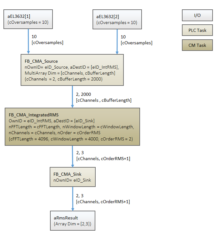
Block diagram
Program parameters
The table below shows a list of important parameters for the configuration of the function blocks that are used.
Buffer size | 2000 |
Channels | 2 |
FFT length | 4096 |
Window size | 4000 |
Sampling rate | 10000 |
Lower frequency bound | 10 |
Upper frequency bound | 1000 |
Order (RMS) | 2 |
Window type | eCM_HannWindow |
Conversion to decibels | FALSE |
Data input
In the sample, oversampling is set to 10, and the PLC task linked to the I/Os is set to 1 ms. This results in a sampling rate of 10 kHz for the data input. According to the sampling theorem, signals in the spectrum up to 5 kHz can now be analyzed correctly, provided the anti-aliasing filter is set correctly in the I/O terminal (see Digitization).
Buffering of the data stream
The input data of the two channels are buffered in the MAIN routine with a source function block. Accordingly, a two-dimensional array with the size [cChannels, cBufferLength] is established. According to DIN ISO 10816-3, frequency range of 10 Hz to 1000 Hz should be evaluated for a rotational speed of more than 600 min-1. The frequency resolution of the frequency analysis (calculated internally in the IntegratedRMS function block) should therefore be well below 10 Hz. If a buffer of 4000 samples is used at a sampling rate of 10 kHz, the resulting frequency resolution is 2.5 Hz. If the Hann window is used, this is formally reduced to 2.5 Hz * 1.5 = 3.75 Hz. In addition, the FFT-length must be a power of 2 and greater than the WindowLength. The BufferLength results from a 50% overlap of the windows. The parameterization in terms of the internal FFT is defined accordingly in the GVL_Constant as follows:
cFFTLength     : UDINT  := 4096;            // length of FFT
cWindowLength  : UDINT  := 4000;            // 96 samples Zero padding
cBufferLength  : UDINT  := cWindowLength/2; // buffer due to 50% overlap
Accordingly, as indicated in the diagram above, an array of the size [2,2000] is obtained for the transfer to the function block FB_CMA_IntegratedRMS.
Frequency-selective RMS value calculation
In the function block FB_CMA_IntegratedRMS an FFT is now calculated, and the RMS value for the transferred frequency range (here 10 Hz to 1000 Hz) is calculated (formally several ranges may be specified). In addition to the RMS values of the direct input signal (when an accelerometer is connected, this is usually an acceleration signal), the function block also calculates the respective integrated parameters, i.e. the RMS value of the vibration velocity and the RMS value of the vibration displacement. The output of the function block is accordingly a 2-dimensional array with [2,3] (2 channels, 3 RMS values per channel).
// define frequency interval according to ISO 10816-3
// e.g. 10 .. 1000 Hz for rotating speed over 600r/min
cfLowerFrequencyLimit : UDINT := 10;
cfUpperFrequencyLimit : UDINT := 1000;

// Parameters for RMS calculation
cOrderRMS   : UDINT := 2;              // acceleration, velocity, and displacement
cChannels   : UDINT := 2;              // ISO 10816-3 says 2 orthogonal sensors
cResult_Length : UDINT := cOrderRMS+1; // nOrder+1 (see InfoSys)
In the settings referred to above the source function block requires 2000/10 = 200 cycles with 1 ms for filling the buffer. The cycle time of the PlcTask_CM should be less than 0.5 * 200 ms, see Task Setting. Since the function block only requires little computing time, the cycle time of the PlcTask_CM is set to 10 ms. The transfer of the data from the source function block to FB_CMA_IntegratedRMS across the task boundaries is handled internally by the Condition Monitoring Library.
Analyzing the result
The results of the RMS value calculation are transferred back to the fast PLC task with 1 ms via a sink function block. All that is required for this purpose is specification of an array in the MAIN routine, which matches the size of the array at the output of FB_CMA_IntegratedRMS, see variable aRMSResult.
The sink function block sets a flag to TRUE when a valid result was calculated, see variable bCalcuate.
(* Push results to sink *)
fbSink.Output2D( pDataOut       := ADR(aRMSResult),
                 nDataOutSize   := SIZEOF(aRMSResult),
                 eElementType   := eMA_TypeCode_LREAL,
                 nWorkDim0      := 0,
                 nWorkDim1      := 1,
                 nElementsDim0  := 0,
                 nElementsDim1  := 0,
                 pStartIndex    := 0,
                 nOptionPars    := 0,
                 bNewResult     => bCalculate );
Based on this flag, the result of the RMS value calculation can then be used in the MAIN routine. In this case the RMS values of the vibration velocity and the vibration displacement are checked for the limit values defined in the ISO standard. Simple IF queries are used in order to keep the sample simple.
The class according to ISO 10816-3 is determined for each two channels and stored in the variables ISOClassIs_Vel (for the classification with regard to the vibration velocity) and ISOClassIs_Displ (for the classification with regard to the vibration displacement). This sample results in four classifications. According to ISO 10816-3, the larger of the two values should be used, if orthogonally arranged sensors are used. In addition, the stricter evaluation should be used if both the vibration displacement and the vibration velocity are used. Accordingly, the worst case of the four evaluations is sought in the source code and defined as output variable ISO_10816_Classification.
Interaction and comments on the sample
In the sample two harmonic vibrations with identical amplitude (4 m/s2) but different frequency (400 Hz and 35 Hz) are defined as input variables. While this acceleration amplitude means classification in class A for a frequency of 400 Hz for an evaluation based on vibration displacement and vibration velocity, for a vibration with 35 Hz an evaluation based on vibration displacement results in class C, for vibration velocity even down to class D. The output variable ISO_10816_Classification therefore corresponds to class D.
If the amplitude of the vibration with 35 Hz is changed to 1 m/s2, the classification changes to B (for vibration velocity) or A (for vibration displacement). Accordingly, the variable ISO_10816_Classification is set to B.
Alternatively, you can leave the amplitude at 4 m/s2 and increase the frequency, e.g. to 800 Hz. This results in Class A classification throughout, and the variable ISO_10816_Classification is set to A.
Requirements
|
Development environment |
Target system type |
PLC libraries to include |
|---|---|---|
|
TwinCAT v3.1.4013 |
PC or CX (x86, x64) |
Tc3_CM, Tc3_CM_Base, Tc3_MultiArray |