FB_ALY_AM8xxxSSD
The AM8xxxSSD enables the analysis of a motor equipped with the Smart System Diagnosis functionality. The built-in encoder records measured values from various internally installed sensors. These include the temperature and humidity in the encoder, as well as the acceleration in the X and Y directions. Various statistical parameters are calculated on the basis of these measured values and threshold monitoring is carried out to detect shocks.
Syntax
Definition:
FUNCTION_BLOCK FB_ALY_SectionTimer_1Ch
VAR_OUTPUT
    ipResultMessage : Tc3_EventLogger.I_TcMessage;
    bError : BOOL;
    bNewResult : BOOL;
    bConfigured : BOOL;
    stHumidity : ST_ALY_LiveMinMaxAvg;
    stTemperature : ST_ALY_LiveMinMaxAvg;
    stXRmsAcceleration : ST_ALY_LiveMinMaxAvg;
    stXKurtosisAcceleration : ST_ALY_LiveMinMaxAvg;
    stXPeakPeakAcceleration : ST_ALY_LiveMinMaxAvg;
    stYRmsAcceleration : ST_ALY_LiveMinMaxAvg;
    stYKurtosisAcceleration : ST_ALY_LiveMinMaxAvg;
    stYPeakPeakAcceleration : ST_ALY_LiveMinMaxAvg;
    bXShockDetected : BOOL;
    nCountXShocks : ULINT;
    fbLastXShockEvent : FB_ALY_DateTime;
    bYShockDetected : BOOL;
    nCountYShocks : ULINT;
    fbLastYShockEvent : FB_ALY_DateTime;
    nCountTotalShocks : ULINT;
END_VAR
Outputs
Name | Type | Description |
|---|---|---|
ipResultMessage | Contains more detailed information on the current return value. For this special interface pointer, it is ensured internally that it is always valid/assigned. | |
bError | BOOL | The output is |
bNewResult | BOOL | When a new result has been calculated, the output is |
bConfigured | BOOL | Displays |
stHumidity | Humidity inside the encoder in %. | |
stTemperature | Temperature inside the encoder in °C. | |
stXRmsAcceleration | RMS of the acceleration in the X direction in g. | |
stXKurtosisAcceleration | Kurtosis of the acceleration in the X direction. | |
stXPeakPeakAcceleration | Peak-to-peak value of the acceleration in the X direction in g. | |
stYRmsAcceleration | RMS of the acceleration in the Y direction in g. | |
stYKurtosisAcceleration | Kurtosis of the acceleration in the Y direction. | |
stPeakPeakAccelerationY | Peak-to-peak value of the acceleration in the Y direction in g. | |
bXShockDetected | BOOL | TRUE if a shock is detected in the X direction. The threshold value of the RMS acceleration is monitored for this purpose. |
nCountXShocks | ULINT | Number of shocks in the X direction. |
fbLastXShockEvent | FB_ALY_DateTime | Timestamp of the last detected shock in the X direction. |
bYShockDetected | BOOL | TRUE if a shock is detected in the Y direction. The threshold value of the RMS acceleration is monitored for this purpose. |
nCountYShocks | ULINT | Number of shocks in the Y direction. |
fbLastYShockEvent | FB_ALY_DateTime | Timestamp of the last detected shock in the Y direction. |
nCountTotalShocks | ULINT | Number of shocks in the X and Y directions. |
 Methods
Name | Definition location | Description |
|---|---|---|
Call() | Local | Method for calculating the outputs for a specific configuration. |
Configure() | Local | General configuration of the algorithm with its parameterized conditions. |
GetChannelOutputArray() | Local | Getting the result array for a specific channel without adding new values. |
Reset() | Local | Resets all internal states or the calculations performed so far. |
SetChannelValue() | Local | Method for transferring values to the algorithm. |
Sample
VAR
fbAM8SSD : FB_ALY_AM8xxxSSD;
    fbSystemTime : FB_ALY_GetSystemTime;

    // Config
    bConfigure : BOOL := TRUE;
    nNumSectionsHumidity : UDINT := 50;
    nNumSectionsTemperature : UDINT := 50;
    nNumBinsRmsAcceleration : UDINT := 30;
    fThresholdRmsAcceleration : LREAL := 1.5;

    // Inputs
    nUpdateCounter AT%I* : ULINT;
    dataSensor0 AT%I* : ULINT;
    dataSensor1 AT%I* : ULINT;
    dataSensor2 AT%I* : ULINT;
    dataSensor3 AT%I* : ULINT;

    // Results
    aTimespansHumidity : ARRAY [1..50] OF LINT;
    aTimespansTemperature : ARRAY [1..50] OF LINT;
    aHistogramRmsAccelerationX : ARRAY [0..31] OF ULINT;
    aHistogramRmsAccelerationY : ARRAY [0..31] OF ULINT;
END_VAR
// Get current system time
fbSystemTime.Call();
// Configure algorithm
IF bConfigure THEN
bConfigure := FALSE;
fbAM8SSD.Configure(nNumSectionsHumidity, nNumSectionsTemperature, nNumBinsRmsAcceleration, fThresholdRmsAcceleration);
END_IF
// Call algorithm
fbAM8SSD.SetChannelValue(1, nUpdateCounter);
fbAM8SSD.SetChannelValue(2, dataSensor0);
fbAM8SSD.SetChannelValue(3, dataSensor1);
fbAM8SSD.SetChannelValue(4, dataSensor2);
fbAM8SSD.SetChannelValue(5, dataSensor3);
fbAM8SSD.Call(tTimestamp := fbSystemTime.tSystemTime);
fbAM8SSD.GetChannelOutputArray(1, ADR(aTimespansHumidity) , SIZEOF(aTimespansHumidity));
fbAM8SSD.GetChannelOutputArray(2, ADR(aTimespansTemperature) , SIZEOF(aTimespansTemperature));
fbAM8SSD.GetChannelOutputArray(3, ADR(aHistogramRmsAccelerationX) , SIZEOF(aHistogramRmsAccelerationX));
fbAM8SSD.GetChannelOutputArray(4, ADR(aHistogramRmsAccelerationY) , SIZEOF(aHistogramRmsAccelerationY));Sample project
The code used in the example section is implemented in the example project below. The link to the required hardware is also shown here.
Download: TC_BSSD
To ensure that the required outputs are available, the drive must be prepared accordingly. This is described in the Preparation section below.
The following packages are required to run the example project:
- TwinCAT Standard
- TF3510 | TwinCAT 3 Analytics Library
- TE5950 | TwinCAT 3 Drive Manager 2
- TF5000 | TwinCAT 3 NC PTP
Preparation
In order for the sensor values to be available for analysis, they must be added to the process image of the drive. This process is described below.
- 1. Create a TwinCAT project.
- 2. Scan the I/Os of the TwinCAT project.
- 3. Add a Drive Manager project to the solution.
- 4. Select the corresponding channel of the drive to which the motor with the B/SSD-capable encoder is connected.
- 5. Select the Advanced tab.
- 6. Further process data can be added in the Process data subitem.
- 7. Add the following process data:
IntSHub: Update counter
IntSHub: Data Sensor 0
IntSHub: Data Sensor 1
IntSHub: Data Sensor 2
IntSHub: Data Sensor 3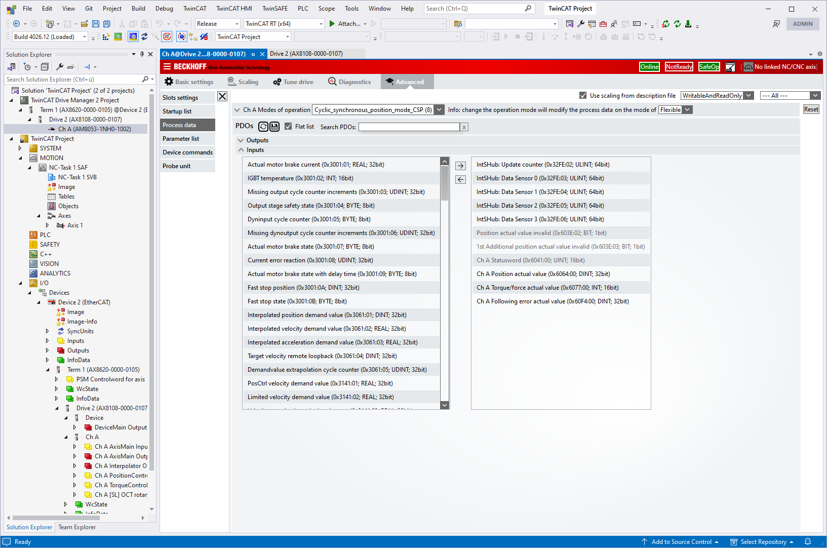
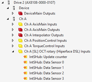
- Once the process data has been added, it is displayed in the I/O node and is available for analysis.
Requirements
Development environment | Target platform | Plc libraries to include |
|---|---|---|
TwinCAT v3.1.4024.0 | PC or CX (x64, x86) | Tc3_Analytics |