Resonance
Most mechanical drive systems are mechanically inhomogeneous.
This can be a belt drive, for example, in which the belt has a different strength and elasticity than other drive axes made of metal.
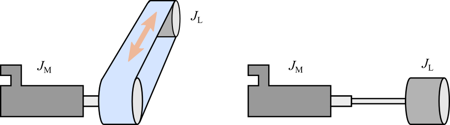
But even drive axes of the same material have different strengths depending on their material thickness.
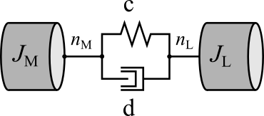
Physically, such systems represent spring-mass systems with "c" as the spring constant and "d" as the attenuation constant. Furthermore, "JM" represents the moment of inertia of a motor and "JL" the moment of inertia of a load.
It must also be taken into account that the user usually does not have information about the position and speed of the load, as the position is usually measured by a position sensor installed in the motor. However, for the user, the behavior on the load side, rather than the motor side, is usually of interest.
For the stability analysis of the drive control, however, the side from which the information flows into the control as feedback is always relevant. This is usually the motor side.
Behavior of a two-mass system
In the following, the ideal behavior of a two-mass system without higher-level control is considered for understanding.
Load side (load speed as actual value related to a torque as setpoint):
If the load speed is related to a given torque of a drive, the following idealized frequency response results for an exemplary two-mass system.
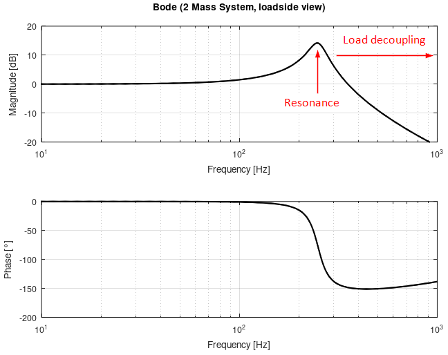
For low frequencies below the resonance frequency, the load can follow the movement of the motor. This is less and less the case for increasing frequencies above the resonance frequency. This is where the load is decoupled from the motor. For this reason, it does not make sense to aim for a controller bandwidth above the resonance frequency when designing the controller.
Motor side (motor speed as actual value in relation to a torque as setpoint):
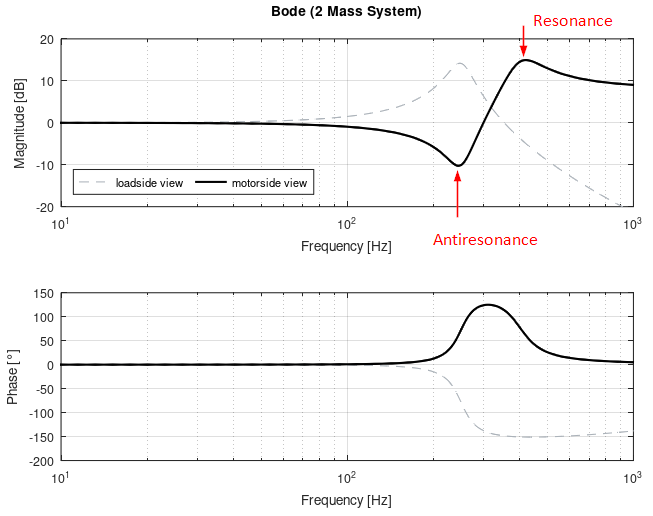
The motor-side transmission behavior of the two-mass system is the decisive behavior for the controller design. (when using the position sensor on the motor).
It shows an anti-resonance at the frequency of the resonance of the load-side behavior. Furthermore, it shows a resonance that lies above the anti-resonance in the frequency range.
The inertia ratio of the load inertia to the motor inertia depends on the distance of the resonance frequency from the anti-resonance frequency.
Behavior of a controlled system with two-mass mechanics
(AX8000 servo drive, basic settings: speed observer: Off, no filters)
The frequency response of a real system with higher-level control and mechanical two-mass behavior is shown below. (The real mechanical system has different parameters than the ideal system shown.)
Furthermore, no filters have been set and the speed monitor is not active.
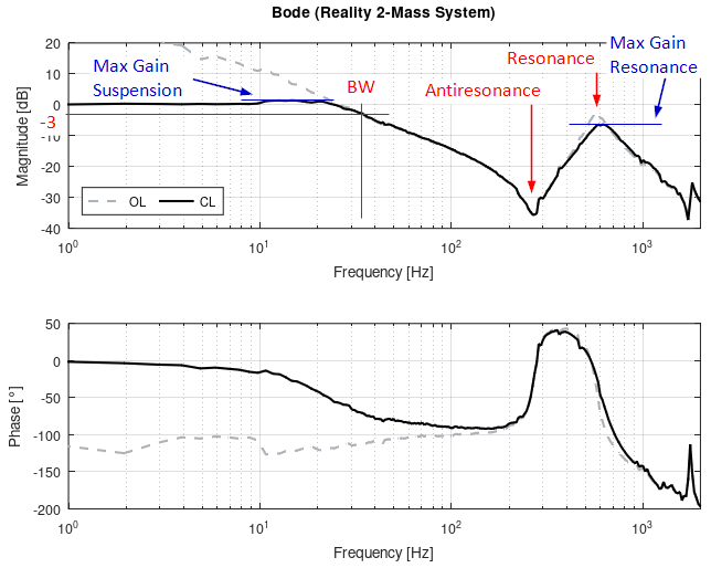
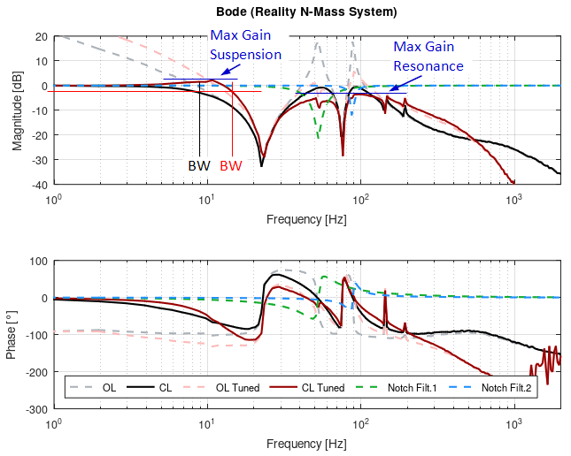
The relevant stability parameters for tuning essentially relate to the response of the mechanical system before and after the leading resonance point.
The maximum gain before resonance (Max. Gain Suspension) can be parameterized to the stiffness of the drive as required. See Stability conditions.
The attenuation of frequency components above the controller bandwidth (BW) is achieved by specifying the Max. Gain Resonance
As a rule, it is desirable for frequency components above the controller bandwidth to have little or no influence on the controller behavior.
For this reason, it is advantageous to attenuate these frequency components sufficiently. Frequently used values for attenuation due to maximum gain resonance are -6dB to -3dB.
The tuning procedure determines the following optimized frequency response, taking the above relationships into account:
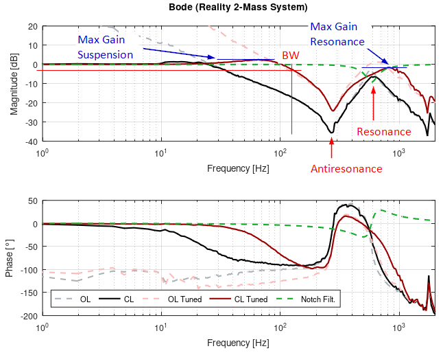
In contrast to the initial plot, the bandwidth (BW) was increased from 33 Hz to over 100 Hz. A notch filter was placed on the resonance frequency to actively attenuate it. The specifications regarding the maximum gains (Max. Gain Suspension (3dB) and Max. Gain Resonance (-3dB)) are adhered to.
Behavior of a controlled system with multi-mass mechanics
Mechanics used in practice often have multi-mass behavior rather than pure two-mass behavior. Such systems can be modeled by connecting several two-mass systems in series.
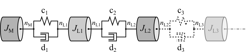
From a practical point of view, the lowest-frequency resonance is relevant for controller tuning, as this is also where the lowest-frequency load decoupling takes place. The following frequency response shows an example of the tuning of such a system.