System Management Bus (SMB)
Newer motherboards possess diagnostic modules via which the temperatures, fan speeds and operating voltages of the PCs can be monitored. These values can be read into TwinCAT with the aid of the ”I/O Device” ”Motherboard SMB (System Management Bus)”. Unfortunately there are currently no unified standards via which these values are made available.
Supports newer motherboards with Intel chipsets. These generally provide access via the PCI-ISA-Bridge PIIX-4. Via the PCI-ISA bridge, access is gained to the register of diagnostic block and the SMB and thereby to the diagnostic data. Individual values can also be determined in the case of other chipsets (if they have, for example, a LM75 or compatible block). Therefore, tests are required to determine which values can be measured on a non-standard board.
The TwinCAT can currently generally recognize the following diagnostic IC's and interpret their data.
- LM78 (National) ( e.g. on ASUS P2B-LS )
- LM78J (National) (e.g. on ASUS P2L97-DS board)
- LM80 (National) ( e.g. on QDI BrillantX IS board )
- LM85B or LM85C (e.g. on Intel's D865GLC or D865GBF board )
- W83781D (Winbond) ( e.g. on ASUS P2B and P2B-F boards )
- W83782D (Winbond) ( e.g. on some EPOX boards)
- W83783S (Winbond) ( e.g. on ABIT BE6 board )
- W83627HF (Winbond) ( e.g. on BECKHOFF CB1050, CB1051,CB2050, CB2051, CB3051, CB3050, CB3053, CB5053, EPOX EP-4B2A or EP-M845B board )
- CX1020 / CX1030 diagnostic IC's (only hardware revision 2.0)
Temperature
All ICs belong to the LM78 family. The LM78 is the basic chip with which all other chips are compared. The Winbond ICs have no internal temperature sensor, in contrast to the LM78 ICs. The temperature is generally measured by the motherboard via the internal temperature sensor. The CPU temperature is measured either via a sensor below the CPU or via the Pentium thermal diode. Other temperature sensors can be connected to external connectors on the board. If the CPU temperature sensor is under the CPU a correction variable must be added to the measured temperature. This depends upon the size of the air gap between the CPU and the sensor. If the temperature is measured via the Pentium thermal diode, the measured value must also be corrected. This correction variable depends upon the type of thermal diode. If there is doubt concerning the measured values, the temperature values can generally be monitored in the BIOS set up.
Fan
All ICs possess inputs allowing the simultaneous measurement of the speed of three fans (LM80, 2 fans only) (CPU FAN, CHASSIS FAN and PWR FAN). The fans must be of a special type with tachometer outputs. These fans generally possess three connection leads. Depending upon the board, the CPU fan may be wired by the manufacturer to a different diagnostic IC input. In most cases, the inputs for two fans (CHASSIS FAN and PWR FAN) are present on the board as external connection pins.
Voltages
The diagnostic ICs can measure positive and negative voltages via the analogue inputs. In general, the IC can measure a max. 4.096V at the input. To measure greater values, voltage divider can be connected upstream. The measured variable is calculated from the upstream resistances and the ADC value (Analogue Digital Converter).
The TwinCAT uses the suggested standard value given by the IC manufacturer as the resistance value for the voltage divider (find in the IC technical documentation). If a board manufacturer has wired other resistance values to the board, the measured values may vary from the real values. The correct voltages can be monitored in the BIOS set up.
Mapping the diagnostic data in the TwinCAT System Manager
The diagnostic data determined is mapped in the TwinCAT System Manager as follows:
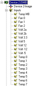
Temperatures are given in °C.
The fan speeds are given in revolutions per minute.
The voltages are given in 1/100 volts. Negative voltages are given as positive values.
Winbond W83782D
Motherboard | EPOX EP-3BXA | |
|---|---|---|
Variable | Hardware/connections description on the board | Comments |
Temp MB | 3TH THERMAL | Temperature of an external sensor. If this is not connected, the variable delivers the value 0. In BIOS this sensor has the description: "Extended JP2". |
Fan 0 | CPU FAN | CPU fan |
Fan 1 | CHASSIS FAN | Chassis fan |
Fan 2 | PWR FAN | Power supply fan |
Volt 2a | Vccp1 | Described as ”Vcore” in BIOS |
Volt 2b | Vtt | Described as ”Vio” in BIOS |
Volt 3.3 | +3.3V voltage |
|
Volt 5 | +5V voltage |
|
Volt 12 | +12V voltage |
|
Volt -12 | -12V voltage |
|
Volt -5 | -5V voltage |
|
Temp 0 | CPU temperature | Temperature at the Pentium thermal diode |
Temp 1 | RT1 | Described as ”System Temperature” in BIOS. A thermal sensor is located on the board (labelled RT1) |
Temp 2 to Temp 7 | not used |
|
Winbond W83627HF
Motherboard | BECKHFOF | EPOX EP-4B2A | EPOX EP-M845B | EPOX IP-4GVI63 | ||||
|---|---|---|---|---|---|---|---|---|
Variable | Hardware/connections description on the board | Comments | Hardware/connections description on the board | Comments | Hardware/connections description on the board | Comments | Hardware/connections description on the board | Comments |
Temp MB | System board temperature | Thermal sensor located on the board near the CPU | not used |
| not used |
| not used |
|
Fan 0 | FAN1 |
| CPU FAN | CPU fan | Fan 3 | In BIOS described as Chasis FAN | CHASIS | In BIOS described as Chasis FAN |
Fan 1 | FAN2 |
| CHASSIS FAN | Chassis fan | (CPU FAN) Fan 1 | CPU fan | CPU | CPU fan |
Fan 2 | FAN3 |
| PWR FAN | Power supply fan | Fan 2 | In BIOS described as Power FAN | PWR | In BIOS described as Power FAN |
Volt 2a | VCCCORE | Described as "CPU Core" in BIOS | Vccp1 |
| Vccp1 |
| Vagp | In BIOS described as Vagp |
Volt 2b | CS_VCCCORE | Described as "GMCH Core" in BIOS | Vtt |
| Vtt |
| Vcore |
|
Volt 3.3 | +3.3V voltage |
| +3.3V voltage |
| +3.3V voltage |
| +2.5V voltage! | In BIOS described as Vdimm |
Volt 5 | +5V voltage |
| +5V voltage |
| +5V voltage |
| +5V voltage |
|
Volt 12 | +12V voltage | ³) | +12V voltage |
| +12V voltage |
| +12V voltage |
|
Volt -12 | -12V voltage | ¹) | -12V voltage |
| -12V voltage |
| -12V voltage |
|
Volt -5 | -5V voltage | ¹) | -5V voltage |
| -5V voltage |
| -5V voltage |
|
Temp 0 | CPU temperature: MAX(core 1..core n) | ²) | CPU temperature | Temperature at the Pentium thermal diode | CPU temperature | Temperature at the Pentium thermal diode | CPU temperature |
|
Temp 1 | System DDR temperature | Thermal sensor located on the board near the memory slots | RT1 | Described as ”System Temperature” in BIOS. A thermal sensor is located on the board (labelled RT1) | TR1 | Described as ”System Temperature” in BIOS. A thermal sensor is located on the board (labelled TR1) | TR1 | Described as ”System Temperature” in BIOS. A thermal sensor is located on the board (labelled TR1) |
Temp 2 | Power Controller Temp. | Supported only with BIOS v0.80 and higher | not used | not used | not used | |||
Temp 3 to 7 | not used | not used | not used | not used | ||||
| FAN4 can not be monitored. ²) DTS (Digital Thermal Sensor). Supported by Core™ Duo/Core™2 Duo. MAX(core 1..core n) and Atom. Temperature at the Pentium thermal diode. |
| The EP-M845B board has 4 fan external connection pins. The Winbond IC allows only measurement of the speed of three fans. The fourth fan ( Fan 4) can not be monitored! |
| ||||
Winbond W83781D
Motherboard | ASUS P2B or P2B-F | |
|---|---|---|
Variable | Hardware/connections description on the board | Comments |
Temp MB | RT1S | Sensor on the board near the Winbond IC (system temperature) |
Fan 0 | CHA FAN | Chassis fan |
Fan 1 | CPU_FAN | CPU fan |
Fan 2 | PWR_FAN | Power supply fan |
Volt 2a | Vccp1 |
|
Volt 2b | Vccp2 |
|
Volt 3.3 | +3.3V voltage |
|
Volt 5 | +5V voltage |
|
Volt 12 | +12V voltage |
|
Volt -12 | -12V voltage |
|
Volt -5 | -5V voltage |
|
Temp 0 | JTPWR | Connection for an external sensor for mains supply temperature |
Temp 1 | JTCPU | Connection for a sensor for the CPU chiller temperature |
Temp 2 to Temp 7 | not used |
|
LM80
Motherboard | QDI BrillantX IS | |
|---|---|---|
Variable | Hardware/connections description on the board | Comments |
Temp MB | Internal temperature sensor in the LM80 IC | Main board temperature |
Fan 0 | CHASFAN | Chassis fan |
Fan 1 | CPUFAN | CPU fan |
Fan 2 | not used |
|
Volt 2a | not used |
|
Volt 2b | +1,48V voltage |
|
Volt 3.3 | +3.3V voltage |
|
Volt 5 | +5V voltage |
|
Volt 12 | +12V voltage |
|
Volt -12 | -12V voltage |
|
Volt -5 | -5V voltage |
|
Temp 0 to Temp 7 | not used |
|
Winbond W83783S and LM75
Motherboard | ABIT BE6 | BOSER HS-6237 Version 2.2 | BOSER HS-6237 Version 3.0 | |||
|---|---|---|---|---|---|---|
Variable | Hardware/connections description on the board | Comments | Hardware/connections description on the board | Comments | Hardware/connections description on the board | Comments |
Temp MB | CON2 | Connection for an external sensor for the CPU chiller temperature | not used |
| JP14 | Temperature of an external sensor. If this is not connected, the variable delivers undefined value. |
Fan 0 | FAN2 | Connection for a fan near the CPU | not used |
| CN2 | In BIOS described as CPUFAN1 speed |
Fan 1 | FAN3 | Connection for a fan near the ISA slot | not used |
| CN25 | In BIOS described as CPUFAN2 speed |
Fan 2 | FAN1 | Connection for a fan near the CPU | not used |
| CN26 | In BIOS described as CPUFAN3 speed |
Volt 2a | +2V voltage |
| not used |
| Vcore |
|
Volt 2b | not used |
| not used |
| not used |
|
Volt 3.3 | +3.3V voltage |
| not used |
| +3.3V voltage |
|
Volt 5 | +5V voltage |
| not used |
| +5V voltage |
|
Volt 12 | +12V voltage |
| not used |
| +12V voltage |
|
Volt -12 | -12V voltage |
| not used |
| -12V voltage |
|
Volt -5 | not used |
| not used |
| not used |
|
Temp 0 | RT1 | System temperature. A thermal sensor is located on the board (labelled RT1) | CPU temperature | LM75 temperature sensor | CPU temperature | In BIOS described as CPU1 temperature To get the real CPU temperature add an offset of ~30°C to the read value! CPUtemp = TwinCATtemp + 30°C |
Temp 1 to Temp 7 | not used |
| not used |
| not used |
|
LM85B or LM85C
Important system requirements:
- The Intel(R) SMBus 2.0 Driver for the ICH5/ICH5-M SMBus Controller-24D3 should be installed and activated;
- Other monitoring applications (e.g Intel's Active Monitor) should be deactivated or deinstalled;
- The BIOS Option "Fan control" should be deactivated;
Motherboard | Intel D865GLC or D865GBF | |
|---|---|---|
Variable | Hardware/connections description on the board | Comments |
Temp MB | Ambient temperature sensor (internal to hardware monitoring and fan control ASIC) | In BIOS described as "System Zone 1 Tempearature". |
Fan 0 | CPU FAN | CPU fan |
Fan 1 | FRONT CHASIS FAN |
|
Fan 2 | REAR CHASIS FAN |
|
Volt 2a | Vccp | In BIOS described as "Vccp" |
Volt 2b | +1.5V voltage | In BIOS described as "+1.5Vin" |
Volt 3.3 | +3.3V voltage |
|
Volt 5 | +5V voltage |
|
Volt 12 | +12V voltage |
|
Volt -12 | not used |
|
Volt -5 | not used |
|
Temp 0 | Thermal diode, located on processor die | Temperature on the Pentium Thermo-Diode. In BIOS described as "Processor Zone Temperature" |
Temp 1 | Remote ambient temperature sensor | In BIOS described as "System Zone 2 Temperature"; |
Temp 2 to Temp 7 | not used |
|
Comment
If the variables Temp 0 or Temp 1 deliver a constant value 0xD0, there may be no external sensor connected to the board (open thermal input).
Winbond W83627HF + LM63
| Beckhoff CX1020 / CX1030 | |
|---|---|---|
Variable | Hardware/connections description on the board | Comments |
Temp MB | Board CX1021 | Board temperature |
Fan 0 | FAN | reserved, not used |
Fan 1 | FAN | CX1030 only: CPU / Case fan else not used |
Fan 2 | FAN | reserved, not used |
Volt 2a | CPU voltage |
|
Volt 2b | CPU voltage |
|
Volt 3.3 | +3.3V voltage |
|
Volt 5 | +5V voltage |
|
Volt 12 | +12V voltage |
|
Volt -12 | not used |
|
Volt -5 | not used |
|
Temp 0 | Board CX1021 | Board temperature |
Temp 1 | not used |
|
Temp 2 | Board CX1020 (LM63) | CPU temperature |
Temp 3 | Board CX1020 (LM63) | Board temperature |
Temp 4 to Temp 7 | not used |
|