FB_KL1501Config
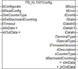
Function block for parameterizing a KL1501: 1-channel counter terminal.
 | This function block does not follow the alternative output format, since the process image shifts during conversion to this format. |
VAR_INPUT
bConfigurate         : BOOL;
bReadConfig          : BOOL;
iSetCounterType      : INT;
bSetBackwardCounting : BOOL;
tTimeout             : TIME;
bConfigurate: A rising edge at this input starts a configuration-sequence. At first the common terminal data like "terminal type", "special type" and "firmware version" will be read. Afterwards the internal registers will be set according to the configurations at the inputs of this function-block. To make sure, the configuration has been successful, the registers will be read and the information will be shown at the outputs of the FB, together with the common terminal-data. As long as this sequence is running, the output bBusy is set to TRUE and no other command, like bReadConfig, will be executed.
bReadConfig: A rising edge at this input starts the reading-sequence only. The common terminal data like "terminal type", "special type" and "firmware version" will be read together with the internal configuration-parameters. The read information will be shown at the FB-outputs afterwards. As long as this sequence is running, the output bBusy is set to TRUE and no other command, like bConfigurate, will be executed.
iSetCounterType: At this input, the dimmer-mode is to be set according to the table below.
bSetBackwardCounting: A TRUE-signal at this input inverts the counting direction.
tTimeout: The commands bConfigurate and bReadConfig have to be successfully executed within this time.
iSetCounterType | Counter type |
|---|---|
0 | 32-bit up/down counter |
1 | 2 x 16-bit up counter |
2 | 32-bit gated counter, gate input low: counter is disabled |
3 | 32-bit gated counter, gate input high: counter is disabled |
VAR_OUTPUT
bBusy             : BOOL;
bError            : BOOL;
iErrorId          : UDINT;
iState            : USINT;
iDataIn0          : UINT;
iDataIn1          : UINT;
iDataIn           : UDINT;
iTerminalType     : WORD;
iSpecialType      : WORD;
iFirmwareVersion  : WORD;
sDescription      : STRING;
sCounterType      : STRING;
bBackwardCounting : BOOL;
bBusy: If a reading- or configuration-sequence is being processed, this output will be set to TRUE.
bError: This output is switched to TRUE as soon as an error occurs during the execution of a command. The command-specific error code is contained in udiErrorId.
iErrorId: Contains the command-specific error code of the most recently executed command. It is set back to 0 by the reactivation of the function block via the bConfigurate or the bReadConfig input. See Error codes.
iState: This value corresponds to the state-variable of the process-data stInData.iState, see VAR_IN_OUT. During command-execution (bBusy = TRUE) this output is set to 0 and remains unchanged. It is thus suitable to evaluate the state of the terminal under normal conditions: disturbing values during configuration and reading due to register-communication will not be shown.
iDataIn0: This value corresponds to the process data stInData.iDataIn0, see VAR_IN_OUT. During command-execution (bBusy = TRUE) this output is set to the value previous to the execution and remains unchanged. It is thus suitable for direct process control: disturbing values during configuration and reading due to register-communication will not be shown.
iDataIn1: This value corresponds to the process data stInData.iDataIn1, see VAR_IN_OUT. During command-execution (bBusy = TRUE) this output is set to the value previous to the execution and remains unchanged. It is thus suitable for direct process control: disturbing values during configuration and reading due to register-communication will not be shown.
iDataIn: This UDINT-variable can be used, if a 32-bit-counter is selected. It consists of the variables iDataIn0 and iDataIn1 (both UINT), whereas iDataIn0 is the less-counting part.
iTerminalType: Contents of register 8. If the right terminal is selected, this value should be 0x05DD (1501dec).
iSpecialType: Contents of register 29: special-type.
iFirmwareVersion: Contents of register 9: firmware-version.
sDescription: Terminal-type, special-version and firmware-version put together to a readable string (e.g. 'Terminal KL1501-0000 / Firmware 1C').
sCounterType: Entered counter type as readable text.
bBackwardCounting: TRUE: The counting direction has been inverted.
VAR_IN_OUT
stInData   : ST_KL1501InData;
stOutData  : ST_KL1501OutData;
stInData: Reference to the structure containing the input process image.
stOutData: Reference to the structure containing the output process image.
Background information
On ARM systems, the structure as a whole cannot be linked to the image of the terminal - the structure variables must be linked individually.
In addition, a new DWORD key must be created in the Windows registry of the development computer, otherwise memory image shifts will occur.
Under "HKEY_CURRENT_USER\Software\Beckhoff\TwinCAT System Manager\On Startup" the key "SubVarOffsByOffs" with the value "1" is inserted.
Afterwards restart the development computer once.
Requirements
Development Environment | Target System | IO Hardware | PLC Libraries to include |
|---|---|---|---|
TwinCAT v2.11 R3/x64 from Build 2254 | PC/CX | KL1501 | TcIoFunctions.Lib ( Standard.Lib; TcBase.Lib; TcSystem.Lib; TcUtilities.Lib are included automatically ) |
TwinCAT v2.11 R3/x64 from Build 2256 | BC | KL1501 | TcIoFunctions.lb6 ( Standard.lb6 will be included automatically ) |
TwinCAT v2.11 R3/x64 from Build 2256 | BX | KL1501 | TcIoFunctions.lbx ( Standard.lbx will be included automatically ) |