FB_HVACPIDCtrl_Ex
Universal PID controller.
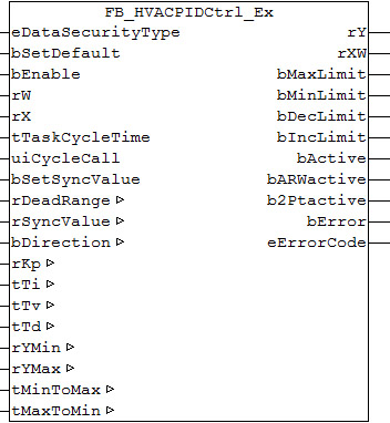
Inputs/outputs
VAR_INPUT
eDataSecurityType: E_HVACDataSecurityType;
bSetDefault      : BOOL;
bEnable          : BOOL;
rW               : REAL;
rX               : REAL;
tTaskCycleTime   : TIME;
uiCycleCall      : UINT;
bSetSyncValue : BOOL;eDataSecurityType:if eDataSecurityType:= eHVACDataSecurityType_Persistent, the persistent VAR_IN_OUT variables of the function block are stored in the flash of the computer if a value changes. For this to work, the function block FB_HVACPersistentDataHandling must be instanced once in the main program, which is called cyclically. Otherwise the instanced FB is not released internally.
A change of value can be initiated by the building management system, a local operating device or via a write access from TwinCAT. When the computer is restarted, the saved data are automatically read back from the flash into the RAM.
Application example:  Example_PERSISTENT.zip
If eDataSecurityType:= eHVACDataSecurityType_Idle the persistently declared variables are not saved in a fail-safe manner.
Notice | |
A cyclically changing variable must never be linked with the IN_OUT variable of a function block, if eDataSecurityType:= eHVACDataSecurityType_Persistent. It would lead to early wear of the flash memory. |
bSetDefault: If the variable is TRUE, the default values of the VAR_IN_OUT variables are adopted.
bEnable: controller activation. At the moment of activation the controller reacts directly to the control deviation without internal synchronization to a value.
rW : setpoint
rX : actual value
tTaskCycleTime: cycle time with which the function block is called. If the function block is called in every cycle this corresponds to the task cycle time of the calling task.
uiCycleCall : call cycle of the function block as a multiple of the cycle time. A zero entry is automatically evaluated as uiCycleCall =1.
Example: tTaskCycleTime = 20 ms, uiCycleCall =10 -> The control algorithm is called every 200 ms. Thus the outputs are also updated only every 200 ms.
bSetSyncValue: a rising edge at this input bSetSyncValue sets the control value rY to the value rSyncValue (VAR_IN_OUT). In addition, the I-component is changed internally. If the I-component doesn't exist (PD controller), the D-component is changed.
VAR_OUTPUT
rY              : REAL;
rXW             : REAL;
bMaxLimit       : BOOL;
bMinLimit       : BOOL;
bDecLimit       : BOOL;
bIncLimit       : BOOL;
bActive         : BOOL;
bARWactive      : BOOL;
b2Ptactive      : BOOL;
bError          : BOOL;
eErrorCode          : E_HVACErrorCodes;
rY : control value. Range limited by rYMin and rYMax.
rXW : control deviation (calculation dependent on control direction)
bMaxLimit : the control value has reached its upper limit value.
bMinLimit : the control value has reached its lower limit value.
bDecLimit : the control value slope has reached its limit value for the maximum decrease, see tMaxToMin (VAR_IN_OUT).
bIncLimit : the control value slope has reached its limit value for the maximum increase, see tMinToMax (VAR_IN_OUT).
bActive : the controller is active, i.e. enabled (bEnable = TRUE) and not in the error state (bError = FALSE).
bARWactive : anti-Reset-Windup function is active.
b2Ptactive : the 2-point behavior of the controller is active.
bError: this output is switched to TRUE if the parameters entered are erroneous.
eErrorCode: contains the command-specific error code. See E_HVACErrorCodes.
VAR_IN_OUT
rDeadRange      : REAL;
rSyncValue      : REAL;
bDirection      : BOOL;
rKp             : REAL;
tTi             : TIME;
tTv             : TIME;
tTd             : TIME;
rYMin           : REAL;
rYMax           : REAL;
tMinToMax       : TIME;
tMaxToMin       : TIME;
rDeadRange: a dead range can be set for the control deviation in order to avoid unnecessary movement and thus premature wear in the valves or damper drives. The P-I-D calculation and thus the control output rY are "frozen" if the value of the control deviation is smaller than half of the dead range rDeadRange. The variable is saved persistently. Preset to 0.
rSyncValue: a rising edge at this input bSync sets the control value rY to this value. In addition, the I-component is changed internally. If the I-component doesn't exist (PD controller), the D-component is changed. The variable is saved persistently. Preset to 0.
bDirection: the control direction of the controller can be changed with the parameter bDirection. If bDirection is TRUE, then the direct control direction is active for cooling operation of the controller. If bDirection is FALSE, then the indirect control direction of the controller is activated for heating operation. The variable is saved persistently. Preset to 0.
rKp: proportional factor gain. Only affects the P-part. The variable is saved persistently. Preset to 1.0.
tTi: integral action time [s]. The I-part corrects the residual control deviation following correction of the P-part. The smaller tTi is set, the faster the controller corrects. The control loop becomes unstable if the time is too short. Larger tTi-times must be entered in order to reduce the integration component. The integral action time should be selected to be longer than the stroke time of the valve or damper drive. A zero value at this parameter disables the I-part. The variable is saved persistently. Preset to 30 s.
tTv: rate time [s]. The larger tTv is, the stronger the controller corrects. The control loop becomes unstable if the time is too long. Often in normal building automation applications only a PI controller is used. A zero value at this parameter disables the D-part. The variable is saved persistently. Preset to 0 s.
tTd : damping time [s]. The variable is saved persistently. Preset to 0 s.
rYMin / rYMax: limiting the working range of the controller. Several other function blocks, e.g. sequencers, require a symmetrical control range (-100 to +100). In the case of a cascade structure, the working range of the master controller determines the setpoint of the slave controller. For example, 15° to 25° as the limitation of the supply air set value for an exhaust/supply air cascade control. The variables are saved persistently. rYMin preset to 0. rYMax preset to 100.
tMinToMax: slope limit [s] of the controller output for increase: tMinToMax in seconds related to a change from rYMin to rYMax. The variable is saved persistently. Preset to 0 s.
tMaxToMin: slope limit [s] of the controller output for decrease: tMaxToMin in seconds related to a change from rYMax to rYMin. The variable is saved persistently. Preset to 0 s
Functional description
Passive behavior (bEnable = FALSE or bError = TRUE)
The outputs are set as follows:
rY | 0.0 |
rXW | 0.0 |
bMaxLimit | FALSE |
bMinLimit | FALSE |
bDecLimit | FALSE |
bIncLimit | FALSE |
bActive | FALSE |
bARWactive | FALSE |
b2Ptactive | FALSE |
In case of error bError is TRUE - eErrorCode indicates the current error code. The internal values for the P, I, and D components are set to 0, also the values for the I and D components of the preceding cycle. This ensures that the control value is "clean" in the first cycle after a restart, i.e. it is calculated without historical values.
Active behavior (bEnable = TRUE and bError = FALSE)
In the first cycle, the I and D components are calculated "clean", i.e. without historical values, as already mentioned. A positive signal on bSetSyncValue sets the I component such that the control value assumes the value rSyncValue. If bEnable and bSetSyncValue are set at the same time, this method can be used to set an initial value from which the controller "sets off". If the I component is not active, the D component is set accordingly. Note that only the rising edge of bSetSyncValue is evaluated internally as this is a setting action. A TRUE signal must be applied again to the input bSetSyncValue for renewed synchronization, for instance with a transfer value. If the I component is active, the controller ensures that it is retained, if the controller output rY is at the limits rYMin or rYMax and about to fall or increase further. This procedure is referred to as anti-wind-up. It ensures that the I-component is always only just sufficiently large to enable the control value to assume values within the limit immediately after a control deviation, without having to deal with an integral component that has become too large.
Control direction
Control direction
If bDirection = FALSE, the control direction of the controller is reversed so that a control deviation of less than 0 causes a change in the control value in the positive direction. This is achieved by a negative calculation of the control deviation:
bDirection | rXW (control deviation) | Control direction |
TRUE | lrX-lrW (actual value-set value) | direct (cooling) |
FALSE | lrW-lrX (set value-actual value) | indirect (heating) |
Anti-Reset-Windup when the maximum or minimum value is reached
If the controller reaches its upper limit at the output and the control deviation is still positive, the integral component will continue to increase, until the control deviation is less than or equal to zero again. This may lead to an unnecessarily large integral component, which would have to be reduced again, if the sign of the control deviation changes and would make the control behavior sluggish. The same applies when the minimum value is reached at the output while the control deviation remains negative.
In order to prevent this, the I part is set in such a way that it reaches the respective limit value lrYmin or lrYMax at the control output in addition with the P and D part.
The further calculation of the P, I and D values is suspended until the sign of the control deviation allows the control range to be entered again; i.e. a control deviation of less than 0.0 when persisting at the maximum limit and or a control deviation of greater than 0.0 when persisting at the minimum limit.
In the PLC cycle of the re-entry also, the output lrY is set by manipulating the I component so that it doesn't move erratically in the control range, but starts to change from the limit of the preceding persistence.
Slope limitation
If the controller is set faster than the actuator, it is unable to follow the controller, which can lead to jitter. It is therefore possible to limit the slope of the control value.
It is based on the following parameters:
tMinToMax : slope limit of controller output for increase: tMinToMax in seconds related to a change from rYMin to rYMax.
tMaxToMin : slope limit of controller output for decrease: tMaxToMin in seconds related to a change from rYMax to rYMin.
This can be used to calculate the maximum change per PLC cycle (maximum increment or decrement).
If the calculated change of the control signal over a PLC cycle is now higher than that set under tMinToMax or tMaxToMin, then the control signal is merely increased or decreased respectively by the maximum increment or decrement.
Internally, the I component is automatically adjusted in the same way (I component of last PLC cycle + maximum increment or I component of the last PLC cycle - maximum decrement).
Dead band
A value of rDeadRange> 0.0 enables the dead range function. If the absolute value of the control deviation is then less than 1/2 rDeadRange, the neutral zone is active, and the P, I and D parts are no longer calculated, resulting in a constant control signal. The components are calculated again and the output signal of the controller changes again when the control deviation is larger again.
This function is intended to avoid an unnecessarily large number of actuating pulses.
2-point control behavior
If the control parameters Ir, rKp, tTn, tTv and tTd are set to 0.0 or t#0s, then the controller has by definition a 2-point behavior.
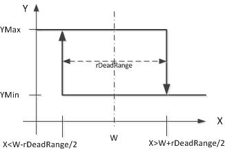
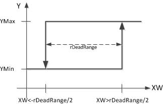
The dead range rDeadRange defines the hysteresis. Switching to the maximum value at the output rY fundamentally takes place when the control deviation rXW is larger than half of the hysteresis value rDeadRange, while switching to the minimum value always takes place when the control deviation rXW is smaller than the negative half of the hysteresis value rDeadRange:
The different calculation methods for the control deviation for direct and indirect control direction result in the following switching behavior in relation to the actual value rX:
- direct control direction (cooling): control deviation = actual value-setpoint rXW = rX-rW
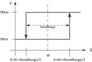
- indirect control direction (heating): control deviation = actual value-setpoint rXW = rW-rX