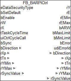
FB_BARPICtrl
Simple PI controller. The control gain has no influence on the I-component.
This PI controller does not work directly with a gain factor Kp, but instead calculates this internally from the so-called proportional band (input rXp) in relation to the control value limits (rYmin and rYmax), from which Kp is then determined internally.
Inputs/outputs
VAR_INPUT
eDataSecurityType: E_HVACDataSecurityType;
bSetDefault      : BOOL;
bEnable          : BOOL;
rW               : REAL;
rX               : REAL;
tTaskCycleTime   : TIME;
uiCtrlCycleCall  : UINT;
bSync : BOOL;eDataSecurityType:if eDataSecurityType:= eHVACDataSecurityType_Persistent, the persistent VAR_IN_OUT variables of the function block are stored in the flash of the computer if a value changes. For this to work, the function block FB_HVACPersistentDataHandling must be instanced once in the main program, which is called cyclically. Otherwise the instanced FB is not released internally.
A change of value can be initiated by the building management system, a local operating device or via a write access from TwinCAT. When the computer is restarted the saved data are automatically read back from the flash into the RAM.
Application example:  Example_PERSISTENT.zip
If eDataSecurityType:= eHVACDataSecurityType_Idle the persistently declared variables are not saved in a fail-safe manner.
Notice | |
A cyclically changing variable must never be linked with the IN_OUT variable of a function block, if eDataSecurityType:= eHVACDataSecurityType_Persistent. It would lead to early wear of the flash memory. |
bSetDefault: If the variable is TRUE, the default values of the VAR_IN_OUT variables are adopted.
bEnable: controller activation
rW : setpoint.
rX : actual value.
tTaskCycleTime: cycle time with which the function block is called. If the function block is called in every cycle this corresponds to the task cycle time of the calling task.
uiCtrlCycleCall : call cycle of the function block as a multiple of the cycle time. . A zero entry is automatically interpreted as uiCtrlCycleCall =1.
Example: tTaskCycleTime = 20ms, uiCtrlCycleCall =10 -> The control algorithm is called every 200 ms. Thus the outputs are also updated only every 200 ms.
bSync: a rising edge at this input sets the (internal) I-component such that rSyncValue is output at the control value output. If the I-component is deactivated by tTn=0ms, however, then this command is ignored.
VAR_OUTPUT
rY        : REAL;
rE        : REAL;
bARW      : BOOL;
bMaxLimit : BOOL;
bMinLimit : BOOL;
bError    : BOOL;
udiErrorId: UDINT;
rY : control value.
rE : control deviation (calculation dependent on control direction)
rEMin : lower control deviation limit value, which results from the input proportional band.
rEMax : upper control deviation limit value, which results from the input proportional band.
bARW: anti-Reset-Windup function is active.
bMaxLimit : the control value has reached its upper limit value.
bMinLimit : the control value has reached its lower limit value.
bError: this output is switched to TRUE if the parameters entered are erroneous.
udiErrorId : contains the error code if the values entered should be erroneous. See error codes.
VAR_IN_OUT
bDirection      : BOOL;
rXp             : REAL;
tTn             : TIME;
rYMin           : REAL;
rYMax           : REAL;
rSyncValue : REAL;bDirection: the control direction of the controller can be changed with the parameter bDirection. If bDirection is TRUE, then the direct control direction is active for cooling operation of the controller. If bDirection is FALSE, then the indirect control direction of the controller is activated for heating operation. The variable is saved persistently. Preset to FALSE.
rXp: proportional band. This defines the internal proportional factor, see below. The proportionality factor or gain affects only the P-part. The variable is saved persistently. Preset to 100.0.
tTn: integral action time in seconds. The I-part corrects the residual control deviation following correction of the P-part. The smaller tTi is set, the faster the controller corrects. The control loop becomes unstable if the time is too short. Larger tTi-times must be entered in order to reduce the integration component. The integral action time should be selected to be longer than the stroke time of the valve or damper drive. A zero value at this input deactivates the I-component. The variable is saved persistently. Preset to 30 s.
rYMin / rYMax: limiting the working range of the controller. Several other function blocks, e.g. sequencers, require a symmetrical control range (-100 to +100). In the case of a cascade structure, the working range of the master controller determines the setpoint of the slave controller. For example, 15° to 25° as the limitation of the supply air set value for an exhaust/supply air cascade control. The variable is saved persistently. Preset to 0.0 or 100.0 respectively.
rSyncValue: a rising edge at this input bSync sets the control value rY to this value. In addition, the I-component is changed internally. If the I-component doesn't exist (PD controller), the D-component is changed. The variable is saved persistently. Preset to 0.0.
Functional description
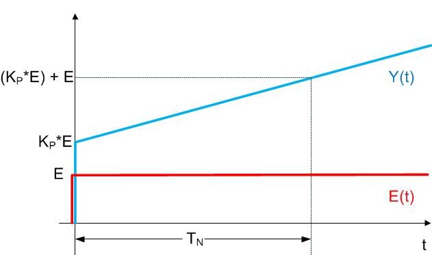
Step response of a simple PI controller, where the control gain has no influence on the integral component.
Response of output Y(t) to a control deviation jump by E: when the control deviation jumps by E, output Y first jumps to KP*E by the proportional component and then grows by a further E in each interval TN.
Note: the controller is designed in such a way that the controller starts at 0, i.e. without the KP*E jump, after a PLC reset or restart.
Basic function
A TRUE signal at the bEnable input activates the function block. The internal control algorithm is now processed. The input value uiCtrlCycleCall specifies the number of PLC cycles after which the internal control algorithm is processed. If uiCtrlCycleCall =1, then the new calculation takes place in each PLC cycle; if, conversely, it is set to 100, then a new calculation of the output values takes place only every 100 PLC cycles. The PLC cycle time is also accounted for in the control value calculation. An incorrect input value leads to incorrect calculation.
The inputs rW (setpoint), rX (actual value), rXp (proportional band) and rTn (integral action time) are the input values of the PI controller. They are used in each calculation cycle for the determination of the output values rY (control value) and rE (control deviation). The control value can additionally be limited by the inputs rYMin and rYMax.
Setting via the proportional band
The adjustment of the gain factor Kp of a controller often harbors the difficulty for the user that there is no size reference to the application. If a heating controller normally operates within the two-figure range, then a flow rate controller can accept values in the five-figure range. It therefore makes sense to represent the Kp factor in such a way that it has a reference to the possible control deviation and change of control value. The P-part of the controller is regarded for the dimensioning of the Kp factor.
The equation for this is:
- Control value = control deviation x gain factor→ Y=E*Kp
this relationship also applies to the changes in the control deviation and the control value:
- Change in control value = change in control deviation • gain factor→ ΔY=ΔE*Kp
Referenced to the minimum and maximum value of the control value, Ymin and Ymax:
- Ymax-Ymin=(E(Ymax)-E(Ymin))*Kp
This difference, E(Ymax)-E(Ymin), is called the proportional band (Xp). Transposed, the equation is then:
- Kp=(Ymax-Ymin)/Xp
The following diagram clarifies the functional interrelationship:
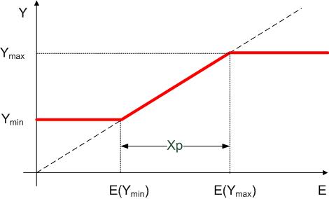
The proportional band Xp therefore indicates the size of the range of the control deviation that leads to an output of Ymin to Ymax from the controller.
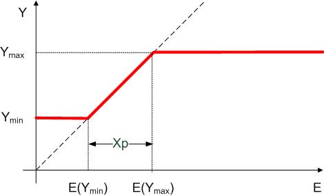
A smaller Xpleads to a steeper function and thus to an increase of the Kp factor. However, the control deviation limit values E(Ymax)-E(Ymin) are shifted:
Control direction
Control direction
If bDirection = FALSE, the control direction of the controller is reversed so that a control deviation of less than 0 causes a change in the control value in the positive direction. This is achieved by a negative calculation of the control deviation:
bDirection | rE (control deviation) | Control direction |
TRUE | lrX-lrW (actual value-set value) | direct (cooling) |
FALSE | lrW-lrX (set value-actual value) | indirect (heating) |
Anti-Reset-Windup (ARW)
If the controller “runs” into this limit, then the I-component is held internally at the final value. If this were not done, then the I-component could adopt very large values without hindrance during the limit case, which would first have to be eliminated again in case of reversal of the direction of action of the controller. This function is called “Anti-Reset-Windup” (ARW). The output bARW is set if this function is active.
Special case: Tn=0 as switch-off of the I-component
From the above step response diagram it can be seen that the influence of the I-component becomes all the weaker, the larger the integral action time Tn is set. As the integral action time approaches infinity, the influence of the I-component is virtually zero. Conversely, an increasingly smaller integral action time allows the influence of the I-component to grow; at Tn=0 the control value would approach infinity. However, this special case is used to cut off the I-component. This is an internally formed exception, since the integral action time belongs directly to the I-component and should also figuratively result in switch-off due to the zero entry.
Synchronization
A positive edge on bSync sets the controller output rY directly to rSyncValue, provided that the controller has been activated by a TRUE signal on bEnable. If this is not the case the positive edge on bSync is ignored.
Error case/function block not activated
If the controller is incorrectly parameterized processing is stopped, the bError output is set and the corresponding error ID is output at udiErrorID, see error codes. The function block is also stopped if the input bEnable is not set. In both cases the outputs are set as follows:
rY | 0.0 |
rE | 0.0 |
bARW | FALSE |
bMaxLimit | FALSE |
bMinLimit | FALSE |