Notes on modulo positioning
Modulo positioning (MC_MoveModulo) is possible irrespective of the axis type. If may be used both for linear or rotary axes, because TwinCAT makes no distinction between these types. A modulo axis has a consecutive absolute position in the range ±∞. The modulo position of the axis is simply a piece of additional information about the absolute axis position. Modulo positioning represents the required target position in a different way. Unlike absolute positioning, where the user specifies the target unambiguously, modulo positioning has some risks, because the required target position may be interpreted in different ways.
Settings in the TwinCAT System Manager
Modulo positioning refers to a modulo period that can be set in the TwinCAT System Manager. The examples on this page assume a rotary axis with a modulo period of 360 degrees.
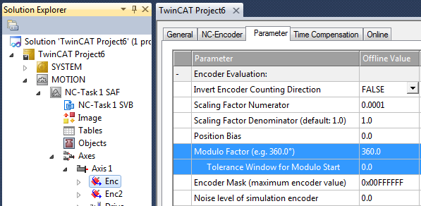
The modulo tolerance window defines a position window around the current modulo set position of the axis. The window width is twice the specified value (set position ± tolerance value). A detailed description of the tolerance window is provided below.
Special features of axis resets
Axis positioning always refers to the set position. The set position of an axis is normally the target position of the last travel command. An axis reset (MC_Reset, controller activation with MC_Power) can lead to a set position that is different from that expected by the user, because in this case the current actual position is used as the set position. The axis reset resets any lag error that may have occurred as a result of this procedure. If this possibility is not considered, subsequent positioning may lead to unexpected behavior.
Example:
An axis is positioned to 90°, with the result that subsequently the set position of the axis is exactly 90°. A further modulo travel command to 450° in positive direction results in a full turn, with the subsequent modulo position of the axis is once again exactly 90°. If an axis reset is then carried out, the set position can randomly be somewhat smaller or slightly larger than 90°. The new value depends on the actual value of the axis at the time of the reset. However, the next travel command will lead to different results. If the set position is slightly less than 90°, a new travel command to 90° in positive direction only leads to minimum motion. The deviation created by the reset is compensated, and the subsequent set position is once again exactly 90°. However, if the set position after the axis reset is slightly more than 90°, the same travel command leads to a full turn to reach the exact set position of 90°. This problem occurs if complete turns by 360° or multiples of 360° were initiated. For positioning to an angle that is significantly different from the current modulo position, the travel command is unambiguous.
To solve the problem, a modulo tolerance window can be parameterized in the TwinCAT System Manager. This ensures that small deviations from the position that are within the window do not lead to different axis behavior. If, for example, a window of 1° is parameterized, in the case described above the axis will behave identically, as long the set position is between 89° and 91°. If the set position exceeds 90° by less than 1°, the axis is re-positioned in positive direction at a modulo start. In both cases, a target position of 90° therefore leads to minimum movement to exactly 90°. A target position of 450° leads to a full turn in both cases.
Effect of the modulo tolerance window: Modulo target position 90° in positive direction
For values that are within the window range, the modulo tolerance window can therefore lead to movements against the specified direction. For small windows this is usually not a problem, because system deviations between set and actual position are compensated in both directions. This means that the tolerance window may also be used for axes that may only be moved in one direction due to their construction.
Modulo positioning by less than one turn
Modulo positioning from a starting position to a non-identical target position is unambiguous and requires no special consideration. A modulo target position in the range [0 ≤; position < 360] reaches the required target in less than one whole turn. No motion occurs if target position and starting position are identical. Target positions of more than 360 degrees lead to one or more full turns before the axis travels to the required target position.
For a movement from 270° to 0°, a modulo target position of 0° (not 360°) should therefore be specified, because 360° is outside the basic range and would lead to an additional turn.
For modulo positioning, a distinction is made between three different directions, i.e. positive direction, negative direction and along shortest path (MC_Direction). For positioning along the shortest path, target positions of more than 360° are not sensible, because the movement towards the target is always direct. In contrast to positive or negative direction, it is therefore not possible to carry out several turns before the axis moves to the target.
 | For modulo positioning with start type "along shortest path", only modulo target positions within the basic period (e.g. less than 360°) are permitted, otherwise an error is returned. |
The following table shows some positioning examples:
Direction | Absolute starting position | Modulo target position | Relative travel path | Absolute end position | Modulo end position |
|---|---|---|---|---|---|
Positive direction | 90.00 | 0.00 | 270.00 | 360.00 | 0.00 |
Positive direction | 90.00 | 360.00 | 630.00 | 720.00 | 0.00 |
Positive direction | 90.00 | 720.00 | 990.00 | 1080.00 | 0.00 |
| |||||
Negative direction | 90.00 | 0.00 | -90.00 | 0.00 | 0.00 |
Negative direction | 90.00 | 360.00 | -450.00 | -360.00 | 0.00 |
Negative direction | 90.00 | 720.00 | -810.00 | -720.00 | 0.00 |
| |||||
Along shortest path | 90.00 | 0.00 | -90.00 | 0.00 | 0.00 |
Modulo positioning with full turns
In principle, modulo positioning by one or full turns are no different than positioning to an angle that differs from the starting position. No motion occurs if target position and starting position are identical. For a full turn, 360° has to be added to the starting position.
The reset behavior described above shows that positioning with full turns requires particular attention. The following table shows positioning examples for a starting position of approximately 90°. The modulo tolerance window (TW) is set to 1°. Special cases for which the starting position is outside this window are identified.
Direction | Absolute starting position | Modulo target position | Relative travel path | Absolute end position | Modulo end position | Note |
|---|---|---|---|---|---|---|
Positive direction | 90.00 | 90.00 | 0.00 | 90.00 | 90.00 |
|
Positive direction | 90.90 | 90.00 | -0.90 | 90.00 | 90.00 |
|
Positive direction | 91.10 | 90.00 | 358.90 | 450.00 | 90.00 | outside TW |
Positive direction | 89.10 | 90.00 | 0.90 | 90.00 | 90.00 |
|
Positive direction | 88.90 | 90.00 | 1.10 | 90.00 | 90.00 | outside TW |
| ||||||
Positive direction | 90.00 | 450.00 | 360.00 | 450.00 | 90.00 |
|
Positive direction | 90.90 | 450.00 | 359.10 | 450.00 | 90.00 |
|
Positive direction | 91.10 | 450.00 | 718.90 | 810.00 | 90.00 | outside TW |
Positive direction | 89.10 | 450.00 | 360.90 | 450.00 | 90.00 |
|
Positive direction | 88.90 | 450.00 | 361.10 | 450.00 | 90.00 | outside TW |
| ||||||
Positive direction | 90.00 | 810.00 | 720.00 | 810.00 | 90.00 |
|
Positive direction | 90.90 | 810.00 | 719.10 | 810.00 | 90.00 |
|
Positive direction | 91.10 | 810.00 | 1078.90 | 1,170.00 | 90.00 | outside TW |
Positive direction | 89.10 | 810.00 | 720.90 | 810.00 | 90.00 |
|
Positive direction | 88.90 | 810.00 | 721.10 | 810.00 | 90.00 | outside TW |
| ||||||
Negative direction | 90.00 | 90.00 | 0.00 | 90.00 | 90.00 |
|
Negative direction | 90.90 | 90.00 | -0.90 | 90.00 | 90.00 |
|
Negative direction | 91.10 | 90.00 | -1.10 | 90.00 | 90.00 | outside TW |
Negative direction | 89.10 | 90.00 | 0.90 | 90.00 | 90.00 |
|
Negative direction | 88.90 | 90.00 | -358.90 | -270.00 | 90.00 | outside TW |
| ||||||
Negative direction | 90.00 | 450.00 | -360.00 | -270.00 | 90.00 |
|
Negative direction | 90.90 | 450.00 | -360.90 | -270.00 | 90.00 |
|
Negative direction | 91.10 | 450.00 | -361.10 | -270.00 | 90.00 | outside TW |
Negative direction | 89.10 | 450.00 | -359.10 | -270.00 | 90.00 |
|
Negative direction | 88.90 | 450.00 | -718.90 | -630.00 | 90.00 | outside TW |
| ||||||
Negative direction | 90.00 | 810.00 | -720.00 | -630.00 | 90.00 |
|
Negative direction | 90.90 | 810.00 | -720.90 | -630.00 | 90.00 |
|
Negative direction | 91.10 | 810.00 | -721.10 | -630.00 | 90.00 | outside TW |
Negative direction | 89.10 | 810.00 | -719.10 | -630.00 | 90.00 |
|
Negative direction | 88.90 | 810.00 | -1078.90 | -990.00 | 90.00 | outside TW |
Modulo calculations within the PLC program
In TwinCAT NC, all axis positioning tasks are executed based on the set position. The current actual position is only used for control purposes. If a PLC program is to calculate a new target position based on the current position, the current set position of the axis has to be used in the calculation (Axis.NcToPlc.ModuloSetPos and Axis.NcToPlc.ModuloSetTurns).
It is not advisable to perform order calculations based on the actual modulo position, which is available in the cyclical axis interface (ModuloActPos and ModuloActTurns). Due to the greater or lesser control deviation of the axis, errors in the programmed sequence, such as undesired rotations, could occur.
Application example
Within a system, a rotational axis carries out an operation. The starting position for each operation is 90°, and with each cycle the axis is to be positioned by 360° in positive direction. Reverse positioning is not permitted for mechanical reasons. Small reverse positioning is acceptable as part of position control movements.
The modulo tolerance window is set to 1.5° in the System Manager. This prevents undesired axis rotations after an axis reset. Since the axis may only be pre-positioned, the motion command MC_MoveModulo with the modulo startup type "positive direction" (MC_Positive_Direction) is used. The modulo target position is specified as 450°, since the original orientation is to be reached again after a full turn by 360°. A modulo target position of 90° would not lead to any motion.
The process starts with a basic positioning movement (MC_MoveModulo) to ensure that the starting position is accurate. The step sequence then changes into an execution cycle. In the event of a fault, the axis is reset with MC_Reset and subsequently (at the start of the step sequence) moved to its valid starting position. In this case, 90° is specified as the target position to enable this position to be reached as quickly as possible. No motion occurs if the axis is already at the starting position.

Alternatively, the reset step may be carried out at the start of the step sequence, so that the axis is initialized at the start of the process.
Requirements
Development environment | Target system type | PLC libraries to include |
|---|---|---|
TwinCAT v3.0.0 | PC or CX (x86 or x64) | Tc2_MC2 |