KL6821 with PC system (CX5120)
This example shows how to write a simple PLC program for DALI in TwinCAT and how to link it with the hardware. The task is to control a single dimmable lamp with a button.
Example: DALI_Sample_KL6821_CX5120.zip
 | The TwinCAT project is available for download as *.zip file. This must first be unpacked locally so that the archive (*.tnzip file) is available for import into the TwinCAT project. |
Hardware
Setting up the components
- 1x Embedded PC CX5120
- 1x digital 4-channel input terminal KL1104 (for the dimming and reset functions)
- 1x DALI terminal KL6821
- 1x KL9010 end terminal
Set up the hardware and the DALI components as described in the documentation.
This example assumes that a Dim button was connected to the first KL1104 input and a Reset button to the second, and that a dimmable lamp is connected to DALI address 0. Set the initial fade rate of the control gear to 7 to achieve suitable dimming.
Software
Creation of the PLC program
Create a new "TwinCAT XAE project" and a "Standard PLC project".
Add the library Tc2_DALI in the PLC project under "References".
Create the following global variables:
VAR_GLOBAL
   bSwitch         AT %I* : BOOL;
   bReset          AT %I* : BOOL;
   stKL6821InData  AT %I* : ST_KL6821InData;
   stKL6821OutData AT %Q* : ST_KL6821OutData;
   stCommandBuffer        : ST_DALIV2CommandBuffer;
END_VAR
bSwitch: Input variable for the Dim button.
bReset: Input variable for the Reset button.
ST_KL6821InData: Input variable for the DALI terminal. (ST_KL6821InData)
ST_KL6821OutData: Output variable for the DALI terminal. (ST_KL6821OutData)
stCommandBuffer: Required for the communication with DALI.
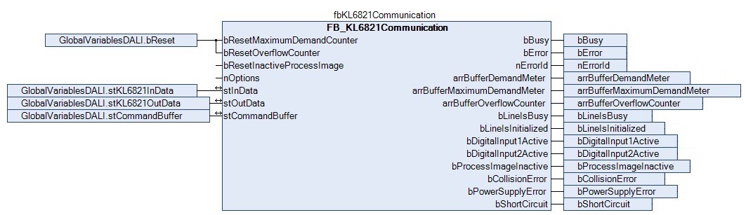
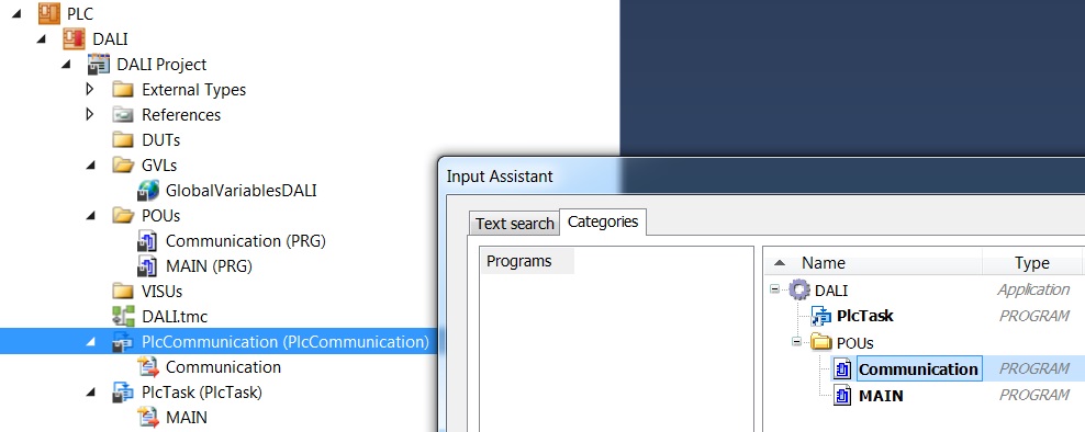
Create a program (CFC) for the background communication with DALI. The function block FB_KL6821Communication is called in the program. In the communication function block ensure that the structures stInData, stOutData and stCommandBuffer are linked.
Create a MAIN program (CFC) in which the function block FB_DALIV2Dimmer1Switch is called up. Connect the input bSwitchDimm of the dimmer function block with the global variable bSwitch and stCommandBuffer with the global variable stCommandBuffer.
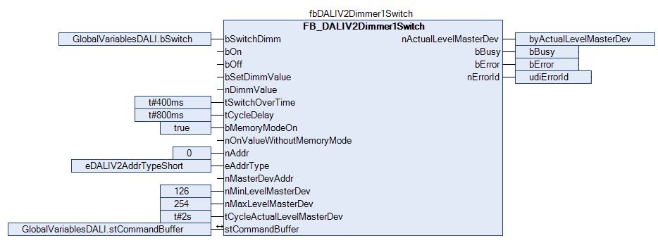
| Parameters nMinLevelMasterDevice and nMaxLevelMasterDevice Make sure that the specified parameters nMinLevelMasterDevice and nMaxLevelMasterDevice match the minimum and maximum values of the device, in order to avoid malfunction. |
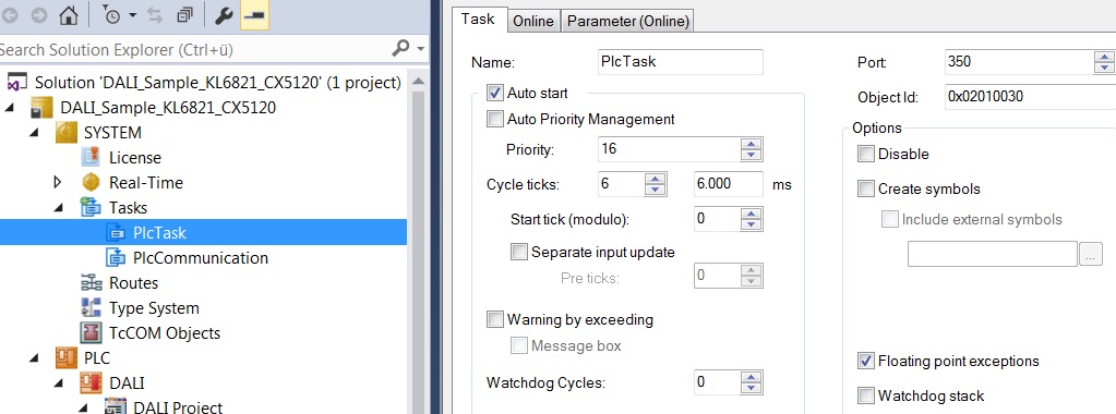
Navigate to the task configuration section and configure the PlcTask. By way of example, the task is assigned priority 16 and a cycle time of 6 ms.
Create a further task for the background communication. Assign a higher priority (smaller number) and a lower interval time to this task than the PLCTask.
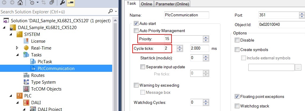
Add the program for the communication to this task. Further information on task configuration can be found in the description of the function block FB_KL6821Communication.
I/O configuration
Select the CX as target system and initiate a search for its hardware. In the project instance within the PLC section, you can see that the input and output variables are assigned to the corresponding tasks.
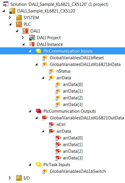
Now link the global variables of PLC program with the inputs and outputs of the Bus Terminals. Create the Solution and enable the configuration.
The lamp can now be controlled by pressing or holding the dimmer button. You can use the Reset button to reset the inputs in arrBufferMaximumDemandMeter and arrBufferOverflowCounter.