"DXD" tab
"DXD" tab
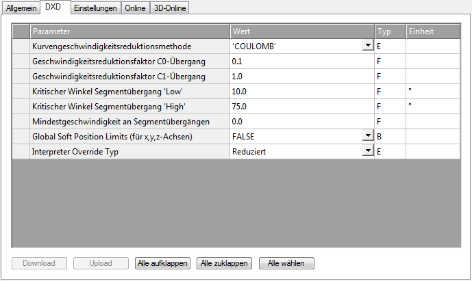
The NCI group parameters are written on the 'DXD' properties page.
Curve velocity reduction method
The curve velocity reduction method is only effective for C0 transition (see Classification of Segment Transitions)
Defines of the curve velocity reduction method
0 Coulomb
1 Cosinus
2 VeloJump
3 DeviationAngle (not yet released)
|
Method |
Description |
|---|---|
|
Coulomb |
The coulomb reduction method is a dynamic process analogous to the Coulomb scattering. |
|
Cosine |
The cosine reduction method is a purely geometrical process.
Reduction scheme:
For full reduction (up to φ = 0), set C0 = 0.0, φlow=0 and φhigh very low but not 0 (e.g. 1.0E-10) |
|
VeloJump |
It is a geometrical procedure for determining the segment transition velocity at a C0 transition. The procedure reduces the path velocity as required, so that the step change in velocity does not exceed the specified limit value. It is calculated based on the following formula: VeloJump factor * cycle time * min(acceleration; deceleration) Further information |
Velocity reduction factor C0 transition
Reduction factor for C0 transitions. The effect depends upon the reduction method.
C0 ∈ [0.0, 1]
Velocity reduction factor C1 transition
First V_link is set equal to the minimum of the two segment set velocities: V_link= min(V_in,V_out). Depending on the geometry types G_in and G_out on the segments to be linked and the plane selections on G_inand G_out, the geometrically induced absolute acceleration jump AccJump in the segment transition is calculated under the velocity V_link. If this is greater than C1 times the path acceleration/(absolute)deceleration AccPathReduced allowed for the geometries and planes, then the velocity V_link is reduced such that the resulting acceleration jump is equal to AccPathReduced. If this value is smaller than V_min, then V_min has priority.
Reduction factor for C1 transitions: C1≥ 0.0
Critical angle, segment transition 'low'
Parameter for φlow. Description of the operational effects, see curve velocity reduction method
Critical angle, segment transition 'high'
Parameter for φhigh. Description of the operational effects, see curve velocity reduction method
Minimum velocity at segment transitions
Each NCI group has a minimum path velocity V_min ≥ 0.0. The actual velocity should always exceed this value. User-specified exceptions are: programmed stop at segment transition, path end and override requests which lead to a velocity below the minimum value. A systemic exception is a motion reversal. With the reduction method DEVIATIONANGLE the deflection angle is φ ≥ φ_h, in which case the minimum velocity is ignored. V_min must be less than the set value for the path velocity (F word) of each segment.
The minimum velocity can be set to a new value V_min ≥ 0.0 in the NC program at any time. The unit is mm/sec.
Global soft position limits (for x,y,z-axes)
Parameters for activating the software limit positions for the path
A description can be found in the annex under Parameterization.
Interpreter override type
Parameter for selecting the path override type (for description see Path override (interpreter override types)).