FB_BACnet_PidControl
Application
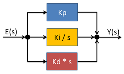
PID controller block in parallel configuration or Ideal form. The controller block serves as a basis for the BACnet loop object (FB_BACnet_Loop).
Block diagram
Use
The controller block must be called cyclically in the PLC program. Please ensure that the cycle time in the moment of the call at input fCtrlCycleTime is transferred as precisely as possible. The cycle time can be determined from the global structure "SystemTaskInfoArr", for example. A possible controller configuration is presented under Example.
VAR_INPUT
fSetpoint       : REAL;
fPresentValue   : REAL;
bReset          : BOOL;
fCtrlCycleTime  : REAL;
fBias           : REAL;
fKp             : REAL;
fKi             : REAL;
fKd             : REAL;
fTp             : REAL:=-1.0;
fMaxOutput      : REAL;
fMinOutput      : REAL;
fSetpoint: setpoint value input (e.g. temperature specification for a room in [°C])
fPresentValue: actual value (e.g. actual room temperature in [°C])
bReset: resets the controller, the output is set to fBias for the duration and limited through fMaxOutput and fMinOutput.
 | If fMinOutput is set to 5% and fBias to 0%, for example, the output fY is set to 5% for the duration of the reset. |
fCtrlCycleTime: cycle time with which the controller is called in seconds [s].
fBias: output offset. This value is offset with the output. The unit must match the unit of the control value (e.g. heating capacity in [%]).
fKp: gain factor P. The control deviation is multiplied with P and added to the output (output behaves proportional to the input deviation).
fKi: integral gain I. The control deviation is multiplied with I (taking into account the cycle time), added to the previous result and added to the output (high control deviation = fast increasing output).
fKd: differential gain D. The control deviation is offset with the previous controller difference, the result multiplied with D (taking into account the cycle time) and added to the output (strong controller variation = strong response).
fTp: damping time for D part (PT1) [s] (if fTp0, then: Tp = fKd / 10).
fMaxOutput: upper limit of the output value fY. The unit must match the unit of the control value (e.g. heating capacity maximum 90%).
fMinOutput: lower limit of the output value fY. The unit must match the unit of the control value (e.g. heating capacity minimum 5%).
VAR_OUPUT
fY            : REAL;
nErrorStatus  : UINT;
fY: Control value (e.g. heating capacity in [%]).
nErrorStatus: Error code, see BACnet_Globals for an overview.
Example
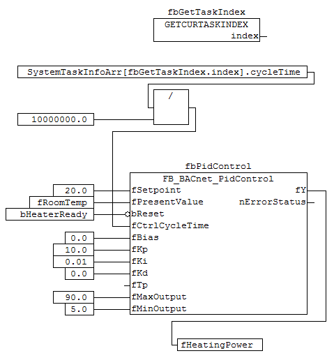
Note re. P = 10 --> a temperature difference of 1 K results in 10% heating capacity, for example
Note re. I = 0.01 --> a temperature difference of 1 K results in 0.01% heating output increase per second, for example
Note re. D = 0 --> no D part.