Emergency stop
This chapter provides basic information on the emergency stop features of your application.
| Once you have fully specified your selected load case, you can enter the emergency stop brake torque. The precise specifications are explained in this section. The purpose of an emergency stop brake torque is to protect against possible personal injuries. The aim is for the application to come to a complete standstill based on an adequately dimensioned emergency stop brake torque, before persons can enter the hazardous range of the machine / application. |
|
|
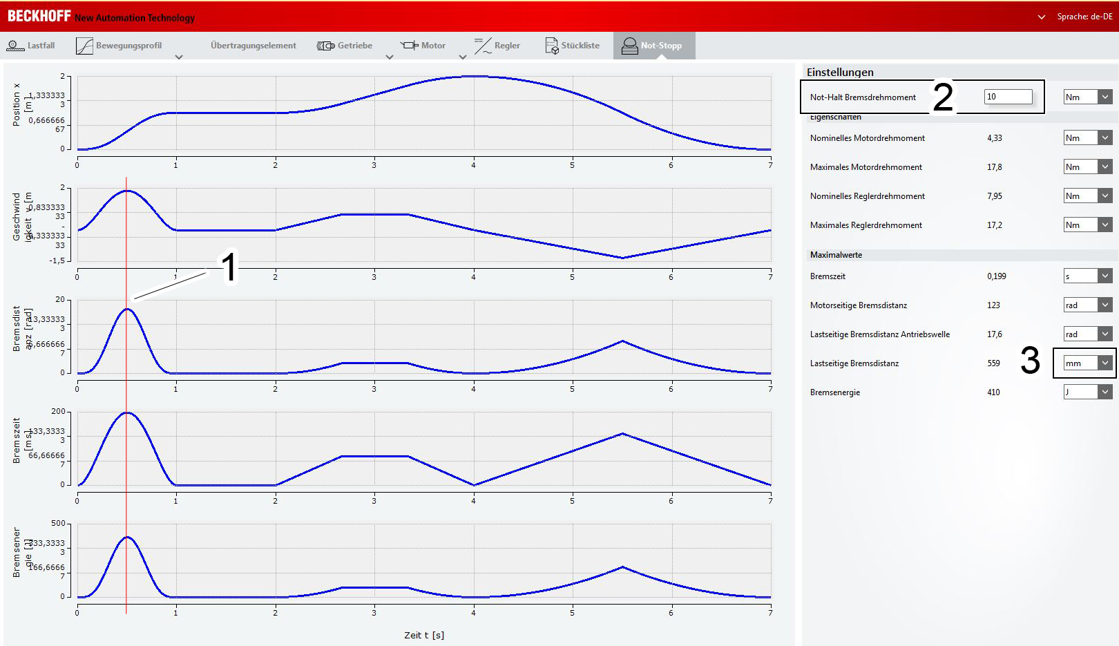
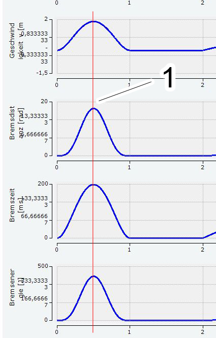
The worst braking case | The settings area |
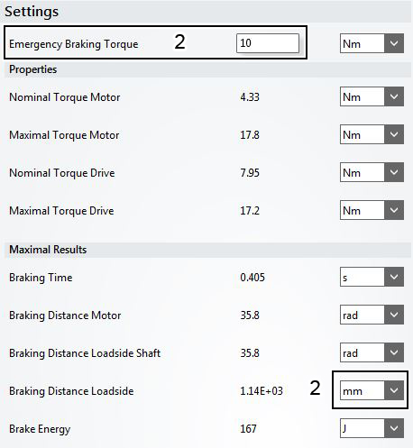
The peak values for velocity, braking distance, braking time and braking energy shown under (1) are worst-case scenarios. The curves show the worst braking case. The curves result from the set emergency stop brake torque. The demarcation line (1) is a notional line to illustrate the peak values of the individual graphs. This boundary line does not appear in TC3 Motion Designer view. | You can enter an emergency stop brake torque in the settings area (2). Please note that the value you enter must be lower than the maximum motor and controller torque. In the worst case, the result of the emergency stop brake torque would be greater than the respective maximum braking energy on the motor and load side. We recommend setting the load-side braking distance (can be calculated from the set emergency stop brake torque) to mm. To change the unit, open the drop-down menu (3) in the settings area and select the required unit. |
|
|
 | Saving your configuration! Once you have dimensioned the emergency stop brake torque in the last step of the application configuration in TC3 Motion Designer, you can save your project. For information on how to open a saved project or created axes please refer to chapter: ”Opening a saved file”. |