Motion profile
This section provides basic information on the motion profile for a load case.
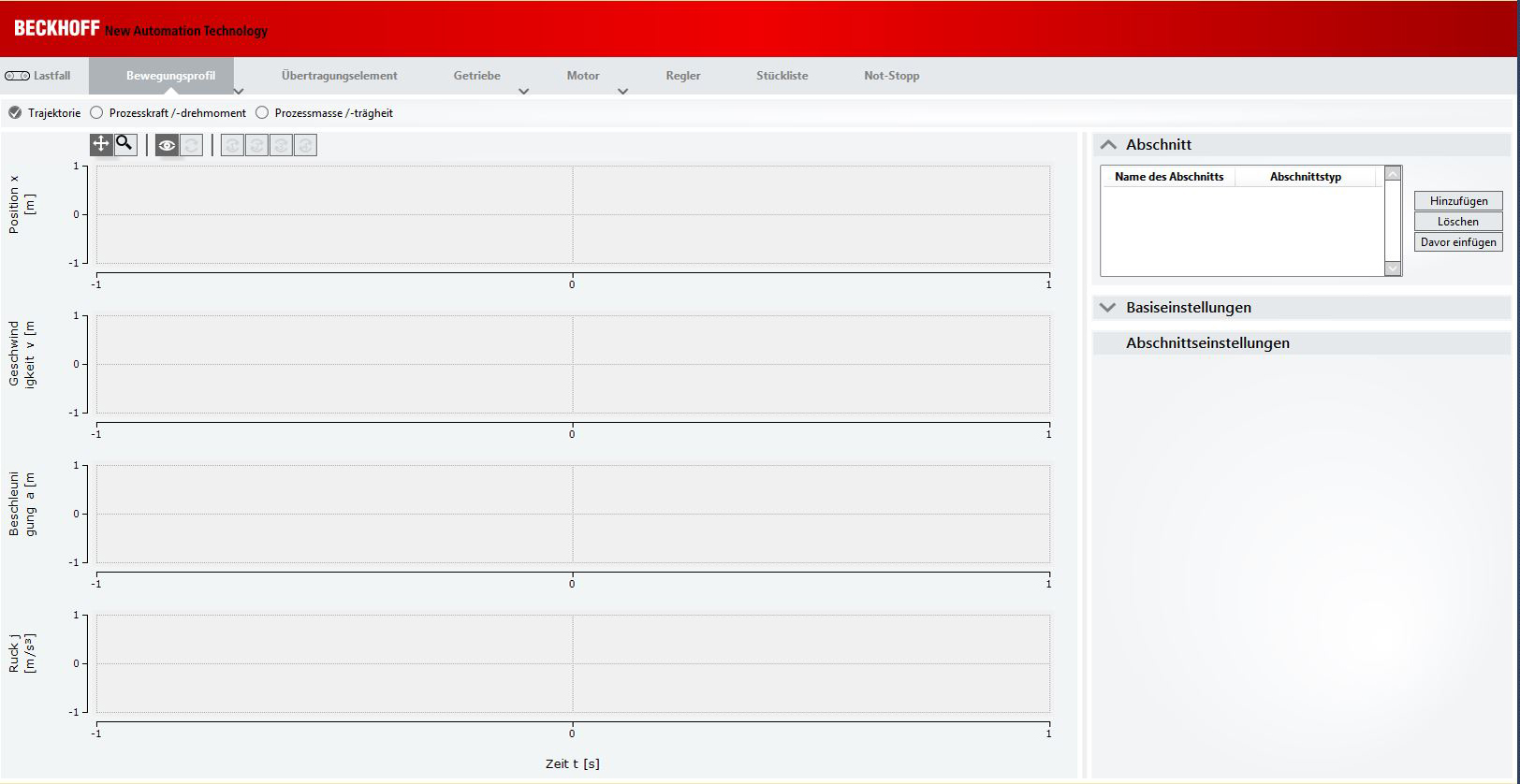
| Once a load case has been selected and specified, a motion profile can be created based on sections. The motion profile illustrates curves along different points. The profiles are specified and evaluated based on certain rules. Currently, only stop-to-stop movements are considered. |
Step 1
Adding a section | |
| To create a profile, you first have to create a section.
|
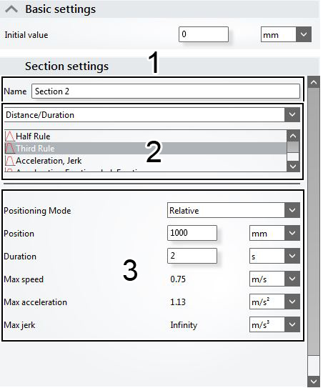
Specifying the section In the settings area you can now specify a section. | |
|
You have successfully specified your section. |
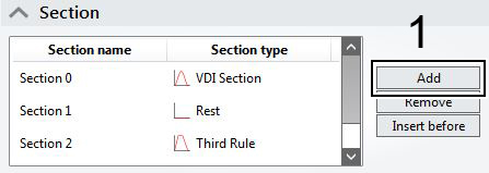
 | Creating several sections! You can create any number of sections within a motion profile. The sections may have different distances/durations. To create a new section, repeat the procedure from step 1. |
Step 2
Display of motion profiles (trajectory) Once you have specified your section, the corresponding profile is displayed. The profile shown illustrates a trajectory. | |
| The following process steps are shown:
|
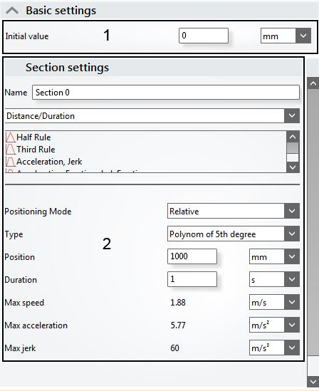
Further basic and section settings The settings area can be found to the right of the process curves. | |
| Under (1) enter:
Under (2) enter:
The setting options are described specific in step 1: "Specifying the section". |
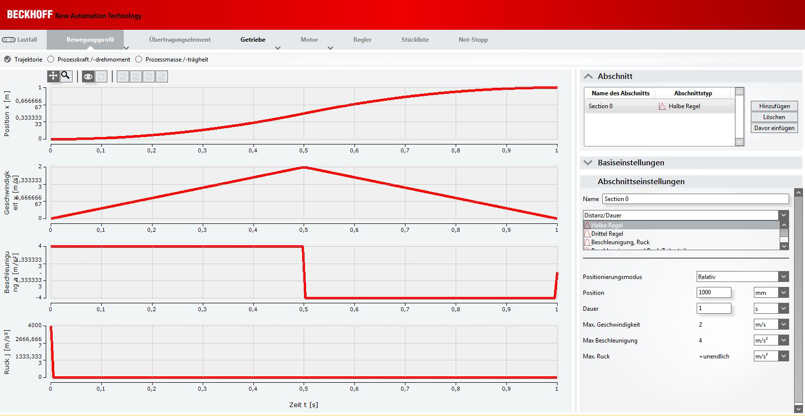
| Selecting the units! All units used in the settings area can be changed via pull-down menus (to the right of the input fields). When a unit is changed, the result is shown in the new unit. |
| Displaying the motion coordinate for the load case! The motion coordinate and the 0 position are displayed in the motion profile for the load case. |
Step 3 If additional or modified process forces occur during the motion (e.g. the cutting force of a milling head), or if the process mass changes (e.g. the transported workpiece is removed from the tool carriage), this change can be reflected in the views. The changes are not tied to the motion sections. The input is time-dependent, which means that additional time sections have to be added. |
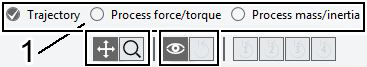
Selecting views In addition to the trajectory view, TC3 Motion Designer offers two further views, which are described in more detail below. | |
| You can select the view in the selection bar (1). |
| |
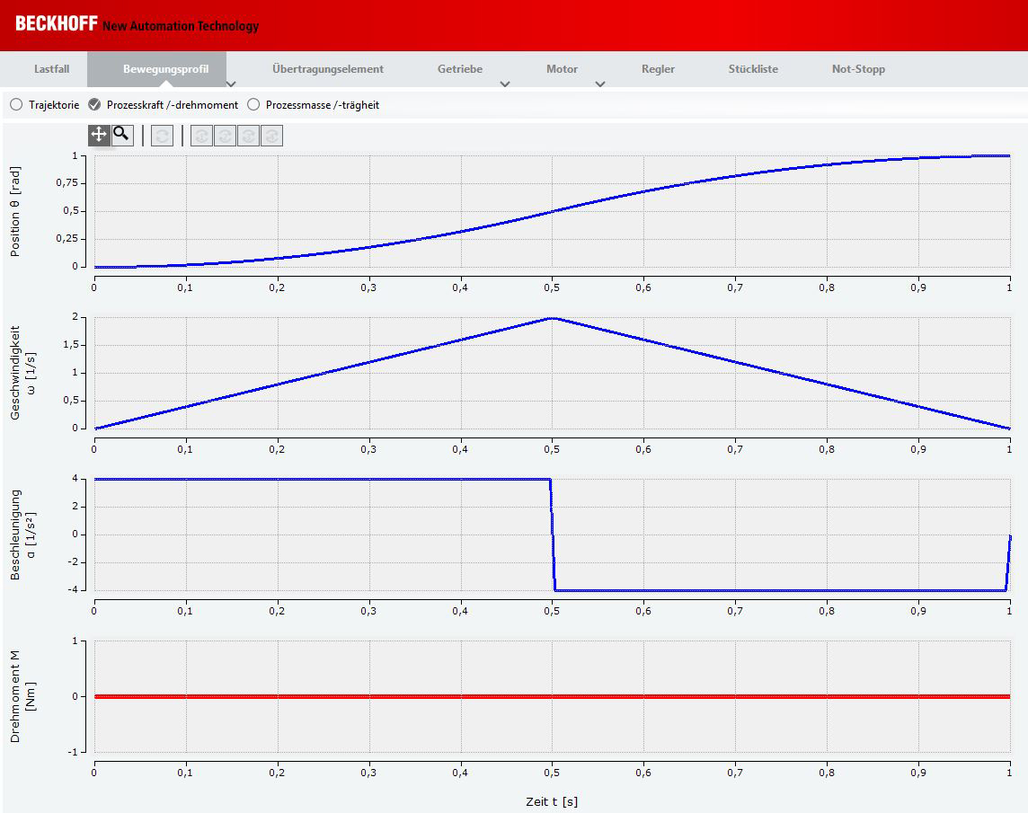
Viewing the process sequences Under the Process force and torque tab you can define modified forces or torques. | |
| In addition, you can create several sections via the section settings. You can switch the view under the view tabs Process mass and Inertia. The following process steps are shown:
|
| |
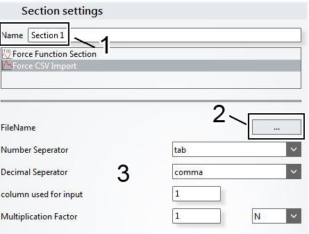
| A variable force can be imported as a CSV file.
The settings from your CSV file are shown in the menu (3). Note: All data can also be supplied manually, if no CSV file is available. |
| Configuration example for a CSV import! Chapter 4.2.1: "Importing a CSV file" illustrates a concrete example of importing a CSV file in your TC3 Motion Designer project. The example is based on version V1.1.0 of the TC3 Motion Designer and Microsoft Visual Studio Shell 2010. |