Interlocks tab
To appear in a predefined faceplate, the Interlocks tab should be configured using the Interlocks Tab property (see table) of the HMI Process Library control. The configuration of the Interlocks tab is explained in the Category: Faceplate chapter.
Depending on the quantity of interlock reasons, the control may have 4, 8, or 16 inputs:
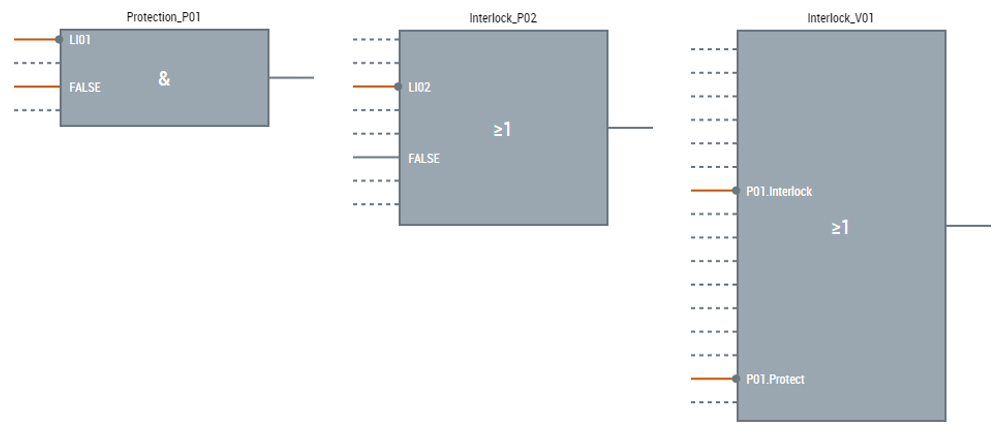
The picture below describes elements of the interlock control:
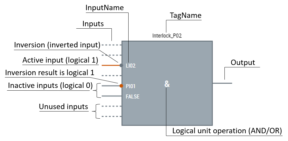
Designation for AND operation is &, OR is ≥1. If the result of input inversion operation is:
- logical 0, it is presented in grey;
- logical 1, it is presented in orange.
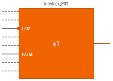
Logical unit operation (AND or OR) is carried out on the control inputs' values, excluding unused inputs. The inversion of the input is considered. If the result of the logical operation is 0, the control stays grey. If the result is 1, it means that the lock is active, and the control and the output turn orange:
Parameters
LockView[N]_Interlocks.usercontrol (where N can be 4, 8 or 16) only has one parameter DataSymbol which should be an instance of the corresponding MTP LockView FB with the corresponding number of the interlock reasons.