Description
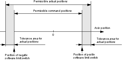
The position of the software limit switches is used to monitor the set and actual positions of an axis. A positive (P-AXIS-00178) and a negative software limit switch (P-AXIS-00177) can be parameterised for each axis.
The positions of the software limit switches are always referred to the axis coordinate system.
Effectiveness
The set positions are monitored during look-ahead, which monitors the actual positions of the position control for travel beyond the software limit switch positions. This is why a distinction is made between software limit switch monitoring in terms of the setpoint or the actual value.
Monitoring of set and actual positions differs by virtue of the fact that, for actual positions, a tolerance for monitoring for travel beyond the software limit switch position (P-AXIS-00179) can be parameterised. Thus, it is possible to prevent for actual positions that slight overshoot does not lead to an error message of the CNC.
Activation
Monitoring of the set and actual positions of an axis by the software limit switch positions is activated as soon as the axis has been referenced. It is then active in all available operating modes. It is permissible for an axis to move to the software limit switch positions.
| |
Monitoring of the set and actual positions for overshoot of the software limit switch positions is not effective in the case of rotatory axes that have been configured as modulo axes. |

Messages
Automatic mode and manual block, axis referenced
If a set position is calculated by an NC block which exceeds a software limit switch position, that NC block is not executed. A message [ID: 120002 or 120003] is generated. The NC program is aborted at this NC block and the axes participating in movement are stopped. The nominal contour is not violated.
The control system must be reset.
If the actual value of the axis position exceeds the software limit switch positions, a message (ID: 70021 or 70022) is generated. The affected axis is braked with a linear speed profile. The nominal contour may be violated if several axes were involved in movement.
The control system must be reset.
Manual operation without parallel interpolation (G200), axis referenced
The travel distance of an axis is limited by the software limit switch positions. The software limit switch position is moved to in the continuous jog mode.
In the incremental jog mode, the step is no longer executed if it leads to violation of the software limit switch position. A message (ID: 150008) is generated. The affected axis can be moved in the opposite direction of travel.
Manual operation without parallel interpolation (G200), axis not referenced
If the axis is not referenced, the positive manual operation offset limit is used for the positive software limit switch position and the negative manual operation offset limit is used for the negative software limit switch position. These are defined in the axis parameter record via the P-AXIS-00137/P-AXIS-00138 (offsetgrenze_neg / offsetgrenze_pos) parameters [Manual mode offset limits].
In the jog mode, the manual operation offset limits are moved to.
In the jog mode, a message (ID: 150008) is generated if the manual operation offset limits are exceeded. The jog step leading to overshoots is not executed. The axis can be moved in the opposite direction.