Installation
| |
Open transformer circuits lead to electric shock and arc flashover! Disregarding this will result in death, physical injury or considerable damage to property!
|

| |
Hazardous voltage can lead to electric shock and burns!
|
| |
Induction of high voltages into the secondary circuit!
|
- Make sure that the working environment is safe during assembly, maintenance and installation work. Interrupt the power supply of the primary conductor and secure against being switched on again inadvertently.
- Open the current transformer and fasten it to the primary conductor with the help of the fixing clasps included in the scope of delivery.
P1 points towards the current source, P2 towards the consumer.
The arrow on the name plate shows the direction of the energy flow.
Caution: Do not close the current transformer yet – high voltages could occur on the secondary connections!
Caution: Makes sure that the cut surfaces of the separated core are clean. Avoid hand contact (sweat)! - Connect the secondary conductors of the current transformer to the measuring device (ammeter, meter, etc.). Observe the operating instructions for the measuring device when doing this.
- Check whether the current transformer is mounted correctly and the secondary conductors are connected correctly.
- Close the current transformer – press together until the closure engages.
- If necessary, switch on the power supply to the primary conductor again.
Connection cable for current transformers
Please note the following minimum power values for current transformers to be connected:
| Rated secondary transformer current | |||||||
|---|---|---|---|---|---|---|---|---|
| 1 A | 1 A | 1 A | 1 A | 5 A | 5 A | 5 A | 5 A |
Cross-section | 0.5 mm² | 1 mm² | 1.5 mm² | 2.5 mm² | 0.5 mm² | 1 mm² | 1.5 mm² | 2.5 mm² |
0.5 m | 0.2 | 0.2 | 0.1 | 0.1 | 1.3 | 0.7 | 0.5 | 0.4 |
1 m | 0.2 | 0.2 | 0.2 | 0.1 | 2.4 | 1.3 | 0.9 | 0.6 |
2 m | 0.3 | 0.2 | 0.2 | 0.2 | 4.8 | 2.4 | 1.7 | 1.1 |
3 m | 0.4 | 0.3 | 0.2 | 0.2 | 7.1 | 3.6 | 2.4 | 1.5 |
4 m | 0.5 | 0.3 | 0.3 | 0.2 | 9.4 | 4.8 | 3.2 | 2 |
5 m | 0.6 | 0.4 | 0.3 | 0.2 | 11.7 | 5.9 | 4 | 2.4 |
10 m | 1.1 | 0.6 | 0.4 | 0.3 | 23.3 | 11.7 | 7.8 | 4.8 |
20 m | 2 | 1.1 | 0.7 | 0.5 | 46.4 | 23.3 | 15.6 | 9.4 |
30 m | 2.9 | 1.5 | 1.1 | 0.7 | 69.6 | 34.9 | 23.3 | 14 |
40 m | 3.8 | 2 | 1.4 | 0.9 | 92.8 | 46.4 | 31 | 18.7 |
50 m | 4.8 | 2.4 | 1.7 | 1.1 | 115.9 | 58 | 38.7 | 23.3 |
100 m | 9.4 | 4.8 | 3.2 | 2 | 231.7 | 115.9 | 77.3 | 46.4 |
Cable length | Minimum rated power in VA for copper connection cables with an operating temperature of 40 °C | |||||||
| Rated secondary transformer current | |||||||
|---|---|---|---|---|---|---|---|---|
| 1 A | 1 A | 1 A | 1 A | 5 A | 5 A | 5 A | 5 A |
Cross-section | 0.5 mm² | 1 mm² | 1.5 mm² | 2.5 mm² | 0.5 mm² | 1 mm² | 1.5 mm² | 2.5 mm² |
0.5 m | 0.2 | 0.2 | 0.1 | 0.1 | 1.4 | 0.8 | 0.6 | 0.4 |
1 m | 0.2 | 0.2 | 0.2 | 0.2 | 2.8 | 1.4 | 1 | 0.7 |
2 m | 0.3 | 0.2 | 0.2 | 0.2 | 5.4 | 2.8 | 1.9 | 1.2 |
3 m | 0.4 | 0.3 | 0.2 | 0.2 | 8 | 4.1 | 2.8 | 1.7 |
4 m | 0.6 | 0.3 | 0.3 | 0.2 | 10.7 | 5.4 | 3.6 | 2.2 |
5 m | 0.7 | 0.4 | 0.3 | 0.2 | 13.3 | 6.7 | 4.5 | 2.8 |
10 m | 1.2 | 0.7 | 0.5 | 0.3 | 26.5 | 13.3 | 8.9 | 5.4 |
20 m | 2.2 | 1.2 | 0.8 | 0.6 | 52.9 | 26.5 | 17.7 | 10.7 |
30 m | 3.3 | 1.7 | 1.2 | 0.8 | 79.3 | 39.7 | 26.5 | 16 |
40 m | 4.4 | 2.2 | 1.5 | 1 | 105.7 | 52.9 | 35.3 | 21.2 |
50 m | 5.4 | 2.8 | 1.9 | 1.2 | 132.1 | 66.1 | 44.1 | 26.5 |
100 m | 10.7 | 5.4 | 3.6 | 2.2 | 264.1 | 132.1 | 88.1 | 52.9 |
Cable length | Minimum rated power in VA for copper connection cables with an operating temperature of 80 °C | |||||||
Maximum cable lengths of the connection cables
The maximum cable length results from a number of factors, including the wire cross-section used, the rated power of the SCT transformers and the evaluation electronics used (e.g. an EtherCAT Terminal from the EL34x3 series), see also the table above.
According to the technical specifications, the rated power of the transformers applies at the transfer point. With the SCT1xxx, SCT2xxx, SCT3xxx, SCT4xxx, SCT7xxx this is the case at the connection terminals, with the SCT6xxx at the end of the connection cable. The transformer must be able to supply the evaluation electronics and the required cable length.
The rated power of the Beckhoff terminals is 0.1 VA. The rest of the power can be absorbed by the cable.
Sample:
SCT6101-0060, rated power: 0.4 VA, 40 °C operating temperature
-> max. power loss according to table (cable + evaluation electronics): 0.3 VA
-> max. cable length with 1.5 mm2 cable cross-section, according to table: ~5 m
SCT6101-0075, rated power: 0.5 VA, 40 °C operating temperature
-> max. power loss according to table (cable + evaluation electronics): 0.4 VA
-> max. cable length with 1.5 mm2 cable cross-section according to table: ~10 m
SCT6101-0100, rated power: 0.75 VA, 40 °C operating temperature
-> max. power loss according to table (cable + evaluation electronics): 0.7 VA
-> max. cable length with 1.5 mm2 cable cross-section, according to table: ~20 m
SCT6101-0150, rated power: 1.0 VA, 40 °C operating temperature
-> max. power loss according to table (cable + evaluation electronics): 0.7 VA
-> max. cable length with 1.5 mm2 cable cross-section, according to table: ~20 m
Design of the SCT6xxx connection cable
The individual wires (S1 and S2) of the SCT6xxx connection cable are brown (S1) and blue (S2). See also the structure of the measuring circuit.
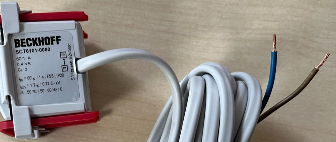 Fig.27: Two-color wires - SCT6xxx connection cable
The lengths of the connection cables for the SCT6xxx variants are listed in the following table:
Current transformer | Connection cable length (and type) |
|---|---|
SCT61xx | 2.5 m (2x 0.5 mm²) * |
SCT63xx | 2.5 m (2x 0.5 mm²) * |
SCT64xx | 2.5 m (2x 0.5 mm²) * |
SCT66xx | 0.5 m (2x 1.5 mm²) * |
SCT67xx | 0.5 m (2x 1.5 mm²) * |
Current transformer | Connection cable length (and type) |
*) The rated power of the transformers applies to all SCT6xxx at the end of the connection cable.
Measuring circuit
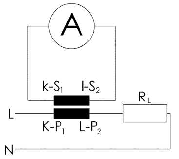 Fig.28: Measuring circuit - SCT6xxx transformer,
brown conductor: S1; blue conductor: S2
Assembly notes
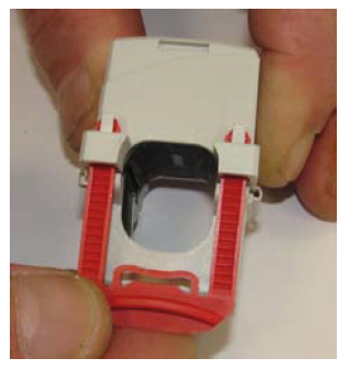 Fig.29: Inserting the fixing clasps
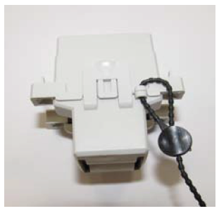 Fig.30: Sealing option with the types SCT63xx, SCT64xx, SCT66xx
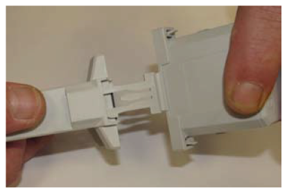 Fig.31: With the SCT67xx types, the lower half of the core can be removed for easier mounting.
 Fig.32: SCT63xx / SCT64xx, snap-on mounting for 35 mm DIN rail, ZB8201-0630