Commissioning
| |
Open transformer circuits lead to electric shock and arc flashover! Disregarding this will result in death, physical injury or considerable damage to property!
|

| |
Hazardous voltage can lead to electric shock and burns!
|
| |
Induction of high voltages into the secondary circuit!
|
Notes on differential current measurement
Damage to the electrical insulation (reduction in insulation resistance) can always result in personal injury. For this reason, residual current devices (RCDs) are installed in many systems. These have a defined tripping range of approx. 15 to 30 mA.
In addition to the residual current circuit breaker, the insulation resistance of the system is also measured as a repeat measurement in accordance with DIN VDE 0105 Part 100 to ensure that the system complies with the safety regulations and installation standards. This measurement can only be carried out on a de-energized system. The guide value for this is four years.
For financial reasons, shorter test intervals are not preferred, even if the system has already aged considerably. In order to detect signs of degeneration in the insulation of the system at an early stage and thus counteract an unplanned shutdown, a differential current measurement is recommended.
This method can detect even very small residual currents, which can be the cause of insulation degeneration. In addition to these residual currents, however, there are other phenomena that complicate the matter. In addition to the residual current or the ohmic leakage current typical of the system, various capacitive leakage currents are also measured. However, these do not provide any information about the insulation status of the system.
These leakage currents are often generated by machines driven by electric motors. Capacitive leakage currents can flow in the large winding capacitance of the motor to the laminated core and thus to the housing. These increase considerably during operation with variable frequency drives and can even lead to damage to the motor ball bearings. The capacitance of long motor cables also leads to leakage currents via the shield. As a result of these leakage currents, a differential current of more than 30 mA is often measured.
Despite these difficulties, it is often possible to recognize a trend in the differential current. This should be interpreted as a sign of an early repeat test in accordance with DIN VDE 0105 Part 100.
The differential current measurement is carried out with the SCT 4xxx differential current transformers. These are compatible with some universal measuring devices or provide a 4-20 mA output with an additional device. There is also the option of connecting a relay.
Measuring circuit
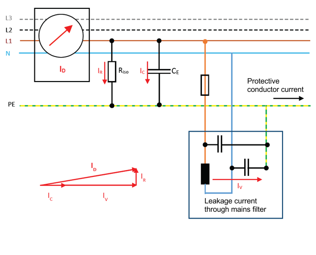 Fig.24: Measuring circuit SCT4xxx transformer
In addition to the leakage current IR via the insulation, the leakage currents IC and IV are also measured using the differential current measurement ID. The capacitive currents flow via the line and load or mains filter capacitances.