Front side and operating elements
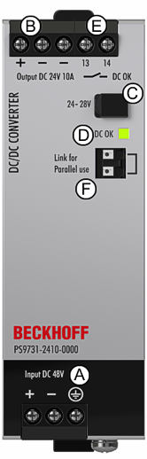 Fig.13: Front PS9731-2410-0000
Input terminals (screw terminals)
Designation (A) | Description |
|---|---|
+ | positive input |
- | negative input |
| PE -> Protective Earth (Ground) connection |

Output terminals (screw terminals)
Designation (B) | Description |
|---|---|
+ | positive output |
- | negative output, two identical - poles |
Output voltage potentiometer
Designation (C) | Description |
|---|---|
Potentiometer | Adjust the output voltage, Factory setting: 24.1 V |
DC-OK LED
Designation (D) | Description |
|---|---|
LED green | DC-OK LED (green) |
DC-OK relay contact (screw terminals)
Designation (E) | Description |
|---|---|
13 / 14 | The DC-OK relay contact is synchronized with the DC-OK LED. |
Link for parallel use (F), “Parallel Use” “Single Use” link
Designation (F) | Description |
|---|---|
Push-in terminals | Connect the two terminals when power supplies are connected in parallel. In order to achieve a sharing of the load current between the individual devices, the “parallel use” regulates the output voltage in such a manner that the voltage at no load is approx. 4 % higher than at nominal load. (See chapter Parallel Use to Increase Output Power for details). |