Output
The output provides an SELV/PELV nominal voltage that is electrically isolated from the input voltage.
The output is electronically protected against overload, no-load and short circuit. In the event of a protection event, audible noises may occur.
The output is designed to supply any type of load, including capacitive and inductive loads.
Output | |||
|---|---|---|---|
Output voltage | Nom. | 24 V |
|
Adjustment range | Min. | 24 - 28 V | Guaranteed value |
Max. | 30.0 V | This is the maximum output voltage that can occur in the end position of the potentiometer in clockwise direction due to tolerances. It is not a guaranteed value that can be achieved. | |
Factory settings | Typ. | 24.1 V | ±0.2%, at full load and with the device cold |
Line regulation | Max. | 10 mV | Between 85 Vac and 300 Vac |
Load regulation | Max. | 100 mV | Between 0 A and 10 A, statistical value, see fig. Output voltage over output current |
Residual ripple and ripple voltage | Max. | 50 mVSS | Bandwidth 20 Hz to 20 MHz, 50 ohm |
Output current - | Nom. | 10 A | At 24 V and 60 °C ambient temperature |
Nom. | 7.5 A | At 24 V and 70 °C ambient temperature | |
Nom. | 9.0 A | At 28 V and 60 °C ambient temperature | |
Nom. | 6.8 A | At 28 V and 70 °C ambient temperature | |
Output current - | Nom. | 15 A | At 24 V and 70 °C ambient temperature |
Nom. | 13.5 A | At 28 V and 70 °C ambient temperature | |
Output power - | Nom. | 240 W |
|
Output power - | Nom. | 360 W |
|
Extra Power time | Typ. | 4 s | Time until the output voltage drops, see Fig. Bonus time over output power |
Recovery time | Typ. | 7 s | Overload-free time until the power manager is reset, see Fig. Extra Power recovery time |
Overload behavior |
| Continuous current |
|
Short circuit current | Max. | 12.5 A | Continuous current, load impedance 100 mOhm |
Max. | 15 A | Continuous current, load impedance 10 mOhm | |
Max. | 21 A | During Extra Power recovery time, load impedance 100 mOhm, | |
Output capacity | Typ. | 7,000 μF | Included in the power supply |
Load feedback | Max. | 35 V | The device is resistant and does not show any malfunction when a load feeds back voltage to the power supply. It does not matter whether the power supply is switched on or off. The absorbed energy can be calculated by means of the built-in large-size output capacitor. |
1) Extra Power
The power supply is designed to support loads with higher short-term power requirements without damage or shutdown.
The short-time duration/bonus time is controlled in hardware by an output power manager.
Extra Power is available repeatedly. Detailed information can be found in the chapter on Repeated pulse load.
If the power supply is loaded with Extra Power for longer than in the bonus time diagram (see fig. Output voltage over output current, typ.; bonus time over output power), the output current is automatically reduced to the continuous output current.
2) Linear derating between +60 °C and 70 °C ambient temperature
Peak current capability (up to several milliseconds)
The power supply can deliver a peak current that is higher than the specified short-term current. This helps to start current-intensive loads or safely operate downstream circuit breakers.
The additional current is supplied by the built-in output capacitors of the power supply. During this process the capacitors are discharged and cause a voltage drop at the output. Further information can be found in the chapter on Peak current capability.
Voltage drops at peak currents | |
|---|---|
Typ. 24 V to 20.5 V | At 20 A for 50 ms, ohmic load |
Typ. 24 V to 18 V | At 50 A for 2 ms, ohmic load |
Typ. 24 V to 14 V | At 50 A for 5 ms, ohmic load |
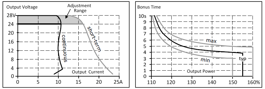 Fig.5: Output voltage over output current, typ.; bonus time over output power
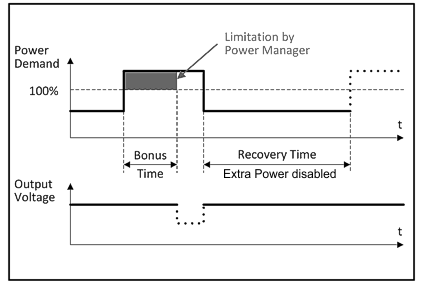 Fig.6: Extra Power recovery time
Extra Power is available as soon as the power is turned on and after an output short-circuit or output overload.
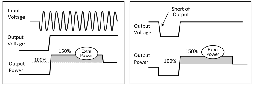 Fig.7: Extra Power after switching on; Extra Power after short circuit or overload