Examples of the synchronization methods in connection with motions
Examples of the synchronization methods in connection with motions
 | To simplify matters, the DIN syntax with channel-specific output is used in the following examples. Parameterization takes place with the familiar P-CHAN-00041 (m_synch[..]) parameter. |
MVS_SVS
Motion is not enabled until the M function is acknowledged by the PLC. Initialization in the channel parameter list
m_synch[..] 0x2
Programming example
N20 G00 X25
N30     X50
N40     X75 M25(M25 of the MVS_SVS type)
N50 G01 X100 F2000
N60 X125 Z100
M30
Fig.1: Synchronization type MVS_SVS
When the block N40 is executed, M25 is output and the program waits for the PLC's acknowledgement before the motion is begun in N40.
MVS_SNS
The subsequent CNC block is not executed until after acknowledgement of the M function by the PLC.
Initialization in the channel parameter list
m_synch[..] 0x4
Programming example
N20 G00 G90 X25
N30     X50
N40     X75 M25(M25 of the MVS_SNS type)
N50 G01 X100 F2000
N60     X125 Z100
M30
Fig.2: Synchronization type MVS_SNS
On execution of the N40 block, M25 is output and the motion is continued. If the acknowledgement of M25 does not arrive in good time, the program stops at the end of N40.
MNS_SNS
Stopping at the end of the block until the M function is acknowledged by the PLC.
Initialization in the channel parameter list
m_synch[..] 0x8
Programming example
N20 G00 X25
N30     X50
N40     X75 M25(M25 of the MNS_SNS type)
N50 G01 X100 F2000
N60 X125 Z100
M30
Fig.3: Synchronization type MNS_SNS
After the motion in N40, the program stops in any case, waiting for the acknowledgement by the PLC after output of M25.
MNE_SNS
Output of the M function is triggered by an event. Motion is not enabled beyond the end of the block until after acknowledgement of the M function by the PLC.
Initialization in the channel parameter list
m_synch[..] 0x20
Programming example
N05 X0 Y0
N10 G108     (Start
measuring edge banding)
N20 G01 X90 Y90
F20
N30 G01 X150 Y150
M33 F8 (M33 of the MNE_SNS type)
N40 G107     (End measuring edge banding)
N50 G00 X200 Y200
M30
Fig.4: Synchronization type MNE_SNS
A measurement event in N30 leads to output of M33. The remaining distance defined by the measurement method is then covered. The program then waits for acknowledgement of M33 by the PLC.
MVS_SLM
Block modal, implicit synchronization at the transition to the next feed motion block (G01, G02, G03). Motion is not enabled beyond the end of this motion block until after acknowledgement of the M function by the PLC.
Initialization in the channel parameter list
m_synch[..] 0x4000
Programming example
N05 M24      (M24,synchronisation type MVS_SLM)
N10 M25 G00X25  (M25,synchronisation type MVS_SLM)
N20 X50
N30 X75
N40 X100
N50 G01 X125 F2000    <--Triggering of M24, M25 before            execution of the motion block
N60 Z100
M30
Fig.5: Synchronization type MVS_SLM
 | If the MVS_SLM M function is programmed in the feed motion block, in conformity with MVS_SVS synchronization takes place before this motion is begun. |
MVS_SLP
Programmed synchronization (#EXPL_SYN)
Initialization in the channel parameter list
m_synch[..] 0x8000
Programming example
N05 M26 G00 X25  (M26, synchronization type MVS_SLP)
N10 M27      (M27, synchronization type MVS_SLP)
N20 X50
N30 X75
N40 X100
N50 G01 X125 F2000N60 #EXPL SYN     Triggering of M26, M27
before             execution of the next block
N70 G00 X0
N80 X0 Y0
M30
Fig.6: Synchronization type MVS_SLP
Behavior of 'late' synchronization (MVS_SLM, MVS_SLP) at program end
The M function remains active even beyond the end of the CNC program if there is no feed motion block after programming of an MVS_SLM M-function or if there is no longer any #EXPL SYN in the current CNC program after programming of an M function with the synchronization method MVS_SLP. Synchronization then takes place in a subsequent CNC program when the trigger condition is reached.
Programming example
%PRG1
N05 M26 G00 X25     (M26, synchronization type MVS_SLM)
N10 M27         (M27, synchronization type MVS_SLP)
M30         (M26, M27 still active at the)
(program end)
%PRG2
N10 G01 F100 X10   <--Triggering of M26 before
execution of the motion
N20 #EXPL SYN      Triggering of M27 before execution
of the next block
M30
If, when a CNC program is started, there are still pending M functions with a 'late' synchronization method from the previous CNC program, synchronization can fundamentally be forced here.
To this end, 1 must be assigned to the channel parameter P-CHAN-00033 (late_sync_ready).
Initialization in the channel parameter list
late_sync_ready 1
Programming example
%PRG1
N05 M26 G00 X25     (M26, synchronization type MVS_SLM)
N10 M27         (M27, synchronization type MVS_SLP)
M30         (M26, M27 still active at the)
(program end)
%PRG2 <--Triggering and waiting for
acknowledgement of M26, M27
before starting of the program
N10 G01 F100 X10
M30MET_SVS, MEP_SVS
Pre-output of the M function in accordance with a specified distance or time and motion enabling only after acknowledgement of the M function by the PLC.
Initialization in the channel parameter list
m_synch[..] 0x01000000 (synchronization MEP_SVS)
m_synch[..]0x02000000 (synchronization MET_SVS)
Programming example
N10 G01 X10 G90 F5000
N20     X20
N30     X30
N40     X40
N50     M96     (M96 MEP_SVS m_pre_outp = 250000,)
(or MET_SVS m_pre_outp = 300000us)
N55     X80
N60     X0
M30
Fig.7: Synchronization types MET_SVS, MEP_SVS
Defining the lead distance or time
The channel parameters P-CHAN-00070 (m_pre_outp[i]) and P-CHAN-00107 (h_pre_outp[i]) are used in combination with the synchronization types MET_SVS and MEP_SVS. The parameters define the value for output before execution of the M/H functions in the path interpolator. The lead time is specified in the case of the MET_SVS type and the lead distance in the case of the MEP_SVS type.
Example for an initialization in the channel parameter list for 2 M functions:
- The user-specific M function M96 is to be output to the PLC 10 millimeters before the synchronization position in the block sequence is reached
- The user-specific M function M97 is to be output to the PLC 40 millimeters before the synchronization time in the block sequence is reached
# Definition of M functions and synchronization methods#======================================================
:
m_synch[96] 0x01000000 MEP_SVS
m_synch[97] 0x02000000 MET_SVS
#
# Pre-output time/distance setting with MET_SVS, MEP_SVS
#=======================================================
m_pre_outp[96] 100000 in 0.1 um
m_pre_outp[97] 40000 in us | In NC program the definition of path or time lead of each M/H function also can be changed by corresponding variables. (e.g. V.G.M_FCT[MNr].PRE_OUTP_PATH, see [PROG]). |
MOS_TS
Output of the M function before NC block, no synchronization. With this type the CNC provides a sample time offset in reference to block transition point.
Because of motion profile sampling with cycle time tzykl the output time of M-function in interpolator is in sample time raster but has at least an maximum time offset of one sample step in reference to the block transition point. The exact output timing can be calculated and done in the PLC by using the sample time offset of M code. (see also [HLI] , pMHTechno^.D_Time).
Initialization in the channel parameter list
m_synch[..] 0x00040000 (MOS_TS)Programming example
N10 G01 X25 G90 F5000
N20     X50
N30     M25 (M25 MOS_TS)
N40     X100
N50     X200
M30
Fig.8: Synchronization type MOS_TS
The output instant of the M code is in sample time raster but not exactly on block limits between the two motion blocks N20 und N40. For controlling the high accuracy output in the PLC, during calculation of the output instant the time offset tcr (fractional part of sample time step, characterizes the exact position of sample time step in reference to block transition point) is considered.
| The function for exact output instant is realized in PLC typically with use of specific high resolution timer hardware. |
Programming example: Exact path synchronous triggering of I/Os
During cutting process a laser (beam width 100µm) shall be switched on/off on exact position. The tolerance is within 10 µs respectively within a ½ beam width (=50 µm). The time related resolution of the CNC interpolation cycle (typical 1 ms) is not sufficient. The problem can be solved by using a specific high resolution timer hardware.
In the system sequence CNC to drive the delay is defined greater than the delay in the system sequence to the laser system.
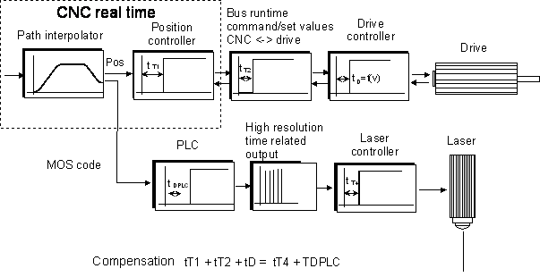 Fig.9: Overview of dead times in system chains
In the current case based on the laser system a typical delay of 800 µs is assumed. For the positioning sequence CNC drive the typical delay is 5 sample cycles ((5 * 1 ms = 5 ms). The positioning system inside the drive operates without position lag (active feedforward control). However, if necessary, the position lag can be estimated. The delay of the positioning sequence for the triggering of the laser is considered in PLC with time TDPLC .
So the provided CNC based M code of the path interpolator is delayed for n cyles inside the PLC. The exact control signal for the laser in the following cycle is calculated within the PLC, based on the interpolation data and the delay and it is created on a hardware terminal with a high basic clock-pulse rate (e.g. 1µs).
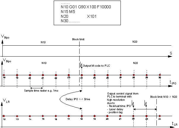 Fig.10: Dead time compensation diagram