Diagnostic LEDs
Coupler Terminal (KL9050)
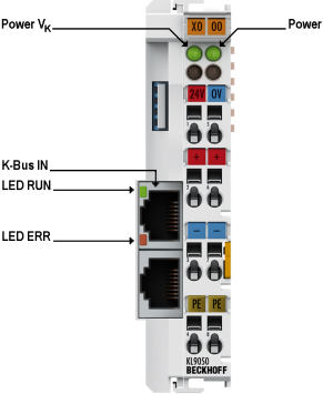
Diagnostic LEDs for power supply
LED | Function | Display | Meaning |
|---|---|---|---|
Power Vk (green) | Indicates whether the supply voltage for the electronics of the Coupler Terminal is switched on. | on | Supply voltage present |
off | Power supply has failed or is switched off | ||
Power (green) | Indicates whether the supply voltage for the I/O terminals of the terminal block is switched on. The power supply of the terminals is via the power contacts. | on | Supply voltage present |
off | Power supply has failed or is switched off |
Diagnostic LEDs on the RJ45 socket for the incoming K-Bus extension (K-Bus IN)
LED RUN (green) | LED ERR (red) | Meaning | Possible causes |
|---|---|---|---|
on | off | Data transmission on the K-bus extension is active |
|
off | on | Data transmission on the K-bus extension is interrupted |
|
off | off | Data transmission on the K-bus extension is interrupted |
|
End Terminal with RJ45 socket (KL9020)
The End Terminal KL9020 has no separate diagnostic LEDs. For diagnosing the K-bus of your bus terminal block, the diagnostic LEDs I/O RUN and I/O ERR of the Fieldbus Coupler installed there are used.
Typical diagnostic LEDs of a Fieldbus Coupler
LED I/O RUN | LED I/O ERR | Meaning | Possible causes |
|---|---|---|---|
on | off | Data transmission on the K-bus is active |
|
off | flashes | Data transmission on the K-bus is interrupted |
|
off | off | Data transmission on the K-bus is interrupted |
|
Behavior in case of an error
If the communication between two or several bus terminal blocks of a K-bus extension system is interrupted
- the green RUN LEDs go out on the RJ45 sockets for the incoming K-bus extension (K-bus IN) on all KL9050s,
- the red ERR LEDs light up on the RJ45 sockets for the incoming K-bus extension (K-bus IN) on all KL9050s,
- the green LED I/O RUN of your Fieldbus Coupler will go out;
- the red LED I/O ERR of the higher-level Fieldbus Coupler will flash rapidly, indicating an interruption of the communication.
Flashing Code
If you now perform a reset for the Fieldbus Coupler, the Fieldbus Coupler searches for the cause of the fault and indicates it as a flashing code via the LED I/O ERR.
A flashing code is made up as follows:
- rapid flicker
- short break
- LED flashes m times for error code m
- short break
- LED flashes n times for error argument n
- short break
Count the error code and the error argument. The flashing code is repeated continuously.
The error code for a K-bus interruption is 4. The error argument indicates the Bus Terminal after which communication was interrupted. Examples are shown in the Fault table for K-bus interruption.