KL9050 - Coupler Terminal
LED | No. | Function |
|---|---|---|
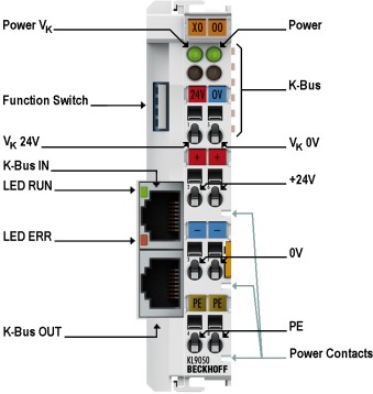
Power Vk, green | A | LED indicates whether the supply voltage for the electronics of the Coupler Terminal is switched on. |
Power, green | C | LED indicates whether the supply voltage for the I/O terminals of the terminal block is switched on. The power supply of the terminals is via the power contacts. |
RUN (K-Bus IN), green | - | LED indicates that data is being transmitted on the K-bus. |
ERR (K-Bus IN), red | - | LED indicating a fault on the K-Bus. |
Terminal point | No. | Function |
|---|---|---|
Vk 24 V | 1 | Input of the +24 V supply voltage for the Coupler Terminal electronics |
+24 V | 2 | Input of the +24 V supply voltage for the power contacts (internally connected to terminal point 6) |
0 V | 3 | Input of the 0 V supply voltage for the power contacts (internally connected to terminal point 7) |
PE | 4 | PE connection (internally connected to terminal point 8) |
Vk 0 V | 5 | Input of the 0 V supply voltage for the Coupler Terminal electronics |
+24 V | 6 | Input of the +24 V supply voltage for the power contacts (internally connected to terminal point 2) |
0 V | 7 | Input of the 0 V supply voltage for the power contacts (internally connected to terminal point 3) |
PE | 8 | PE connection (internally connected to terminal point 4) |
Interface | Function |
|---|---|
K-bus In | RJ45 socket for the incoming K-bus extension |
K-bus OUT | RJ45 socket for the continuing K-bus extension |
K-bus | Internal K-bus of the Bus Terminal block |
Power Contacts | Internal power contacts of a bus terminal block |
Switch for the termination resistor of the Coupler Terminal |