Settings
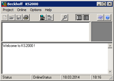
Start the KS2000 Configuration Software.
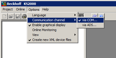
Communication channel
The communication between KS2000 and the KL6224 can take place either via the fieldbus (via ADS) or via a serial cable (via COM interface).
Click on Options/Communication channel to select the communication channel.
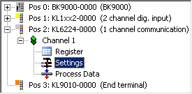
Login
Click on Login. 
The fieldbus station is displayed as a tree structure.
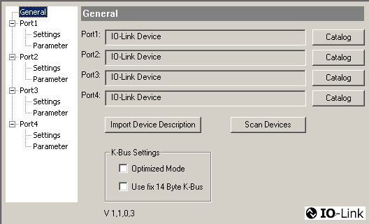
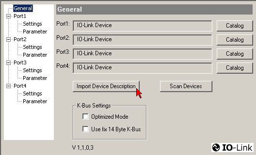
Insert the IO-Link devices
There are three options to integrate an IO-Link device:
- Automatic scan of the IO-Link ports, [Scan devices] button
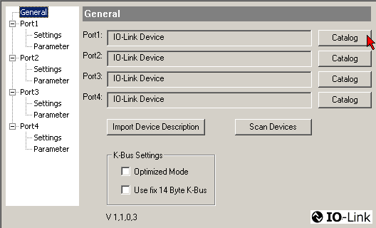
- Manual insertion via catalog, [Catalog] button
- Import the device description, [Import Device Description] button
Automatic scan of the IO-Link ports
Connect the IO-Link sensor to the KL6224.
Switch on the Bus Coupler with the KL6224.
Click on Login to connect to the fieldbus station and read the modified KL6224 process image.
In the General dialog click on the [Scan devices] button.
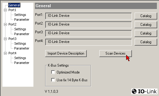
 | Communication Mode For scanning, the Communication mode must not be set to Communication (Port1/Settings). |
The detected IO-Link devices are displayed, and the required process data are created.
Manual insertion via catalog
In the General dialog click on the [Catalog] button.
Here you can
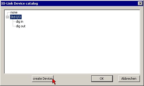
use the create Device dialog to manually create an IO-Link device
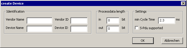
with the main communication parameters.
Import the device description
In the General dialog click on the [Import Device Description] button.
The XML files for the IO-Link devices are stored in the IO-Link folder of the KS2000 (e.g. under Windows 7 in the folder C:\Program Files (x86)\KS2000_V4\IOLink)
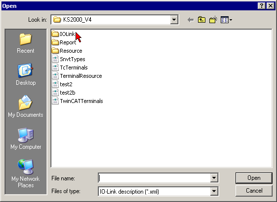
Select the XML file for the required sensor and open it.
Now continue scanning the IO-Link ports (see above).
The detected IO-Link devices are displayed, and the required process data are created.
| Always import IODD Always read in existing IODDs before scanning or manually inserting IO-Link devices, in order to obtain further sensor-specific information. |
K-bus interface
Please note: When changing IO-Link devices the following message may occur.
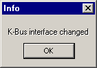
This message indicates that the K-bus interface of the KL6224 has changed, because the connection of a further IO-Link device has changed the process image of the KL6224.
However, this message does not affect the integration of IO-Link devices.
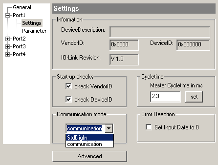
IO-Link port settings
In the General dialog click on Settings for the required port.
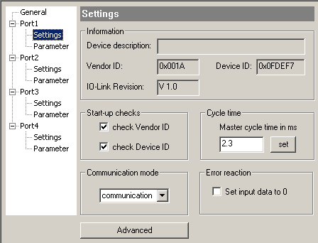
StartUpChecks
This parameter can be used to specify that the vendor ID and the device ID should be checked when the IO-Link device starts up.
CycleTime
Specifies the cycle time for the IO-Link master
Communication mode
An IO-Link device can be operated in different modes. The default mode for IO-Link devices is Communication.
Error reaction
If this checkbox is checked, the input data are set to 0 in the event of an error.
Advanced
Click on [Advanced] to open the dialog for the advanced settings.
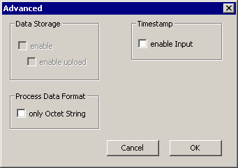
Data Storage
Please note the sensor versions:
- V1.0: Data Storage is not supported
- V1.1: Data Storage is supported: in delivery state (default) data (sensor parameters) are stored.
Process Data Format
Here you can adjust the process data format.
If the checkbox only Octet String is checked, complex data types (process data) are created as octet string in the interest of simplification.